General information
product brand nameSITOP
product type designationPSU8400
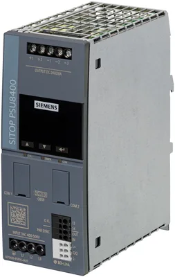
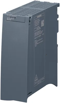
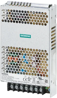
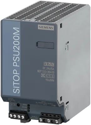
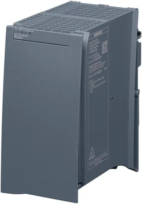
product designationPower supply SITOP PSU8400
type of current supply24 V/20 A
input
type of the power supply network3-phase AC or DC
phase number3
voltage curve at inputAC/DC
minimum rated value400 V
maximum rated value500 V
initial value323 V
full-scale value576 V
supply voltage at ACDerating 323 ... 360 and 550 ... 576 V
supply voltage at DC500 ... 550 V
input voltage at DC450 ... 600 V
at 50 Hz400 V
at 60 Hz500 V
line frequency50/60 Hz
line frequency47 ... 63 Hz
wide range inputYes
buffering time for rated value of the output current in the event of power failure minimum30 ms
operating condition of the mains bufferingat Vin = 400 V
at rated input voltage 400 V0.9 A
at rated input voltage 500 V0.7 A
at rated input voltage 500 V1.4 A
at rated input voltage 550 V1 A
current limitation of inrush current at 25 °C maximum3 A
I2t value maximum0.1 A²·s
fuse protection typenone
fuse protection type in the feederrequired: 3-pole coupled miniature circuit breaker (IEC 898; for UL: UL489-listed/category DIVQ) characteristic C: 4 - 16 A, or circuit breaker (e.g. 3RV2011-1EA10, 3RV2711-1ED10 (UL489)), alternatively slow fuses (for UL: UL248-listed); suitable DC protection must be provided when operating with DC power supply.
output
voltage curve at outputControlled, isolated DC voltage
product function output voltage controlledYes
product function output voltage stabilizedYes
number of outputs1
output voltage at DC rated value24 V
at output 1 at DC rated value24 V
at output 1 at DC24 V
output voltage adjustableYes; via display and IO-Link interface
adjustable output voltage22 ... 28 V; Derating > 24 V: max. 480 W power output (576 W to 45°C)
relative overall tolerance of the voltage3 %
on slow fluctuation of input voltage0.2 %
on slow fluctuation of ohm loading0.2 %
maximum20 mV
maximum100 mV
display version for normal operationdisplay and 3-color LED for operating, fault and communication status
type of signal at outputrelay contact (NO contact, contact rating DC 30 V/0.1 A) for "24 V O.K."; configurable via IO-Link
behavior of the output voltage when switching onNo overshoot of Vout (soft start)
response delay maximum0.5 s
typical50 ms
maximum50 ms
rated value20 A
per output20 A
at output 1 rated value20 A
rated range0 ... 20 A; 24 A up to 45 °C; +60 ... +70 °C: derating 3.75%/K
supplied active power typical480 W
at short-circuit during operation typical60 A
at short-circuit during operation25 ms
at short-circuit during operation typical24 A
bridging of equipmentYes; active load distribution via control contact or inclined output characteristic can be selected via display and IO-Link
number of parallel-switched equipment resources for increasing the power2
efficiency
efficiency in percent96 %
at rated output voltage for rated value of the output current typical20 W
during no-load operation maximum3.3 W
closed-loop control
relative control precision of the output voltage with rapid fluctuation of the input voltage by +/- 15% typical1 %
relative control precision of the output voltage at load step of resistive load 10/90/10 % typical3 %
maximum3 ms
protection and monitoring
design of the overvoltage protectionmax. 32 V
property of the output short-circuit proofYes
design of short-circuit protectionconstant current characteristic or latching shutdown (selectable via display and IO-Link)
response value current limitation15 ... 24.5 A
design of the current limitationadjustable via display and IO-Link
in normal operation150 % IaRated up to 5 s/min (configurable via display and IO-Link)
maximum28 A
typical24 A
display version for overload and short circuitdisplay and 3-color LED for operating status
design of the reset device/resetting mechanismvia display and IO-Link
interfaces
product function communication functionYes
design of the interfaceIO-Link
IO-Link protocolYes
IO-Link transfer rateCOM3 (230.4 kBaud)
number of IO-Link ports1
point-to-point cycle time between master and IO-Link device minimum10 ms
data volume of the address range of the outputs with cyclical transfer for all IO-Link ports maximum3 byte
data volume of the address range of the inputs with cyclical transfer for all IO-Link ports maximum13 byte
protocol between master and IO-Link device Version 1.1Yes
safety
galvanic isolation between input and outputYes
galvanic isolationOutput voltage: SELV, ES1 (IEC 62368-1), DVC As (IEC 61204-7)
operating resource protection classClass I
maximum3.5 mA
protection class IPIP20
EMC
for emitted interferenceEN 55022 Class B
for mains harmonics limitationEN 61000-3-2
for interference immunityEN 61000-6-2
standards, specifications, approvals
CE markingYes
UL approvalYes; cULus-Listed (UL 508, CSA C22.2 No. 107.1), File E197259
UKCA markingYes
EAC approvalYes
Regulatory Compliance Mark (RCM)Yes
NEC Class 2No
SEMI F47Yes
CB-certificateYes
MTBF at 40 °C440 000 h
standards, specifications, approvals hazardous environments
IECExNo
ATEXNo
ULhazloc approvalNo
UKEXNo
CCC for hazardous zone according to GB standardNo
FM registrationNo
standards, specifications, approvals marine classification
shipbuilding approvalNo
American Bureau of Shipping Europe Ltd. (ABS)No
French marine classification society (BV)No
Det Norske Veritas (DNV)No
Lloyds Register of Shipping (LRS)No
standards, specifications, approvals Environmental Product Declaration
Environmental Product DeclarationYes
total541.3 kg
during manufacturing33.8 kg
during operation506.8 kg
after end of life0.3 kg
ambient conditions
during operation-40 ... +70 °C; with natural convection
during transport-40 ... +85 °C
during storage-40 ... +85 °C
environmental category according to IEC 60721Climate class 3K3, 5 ... 95% no condensation
connection method
type of electrical connectionscrew-type terminals and push-in terminals
at inputL1, L2, L3, PE: 1 screw terminal each for 0.2 ... 4 mm² single-core/finely stranded
at output+1, +2, -1, -2, -3: 1 screw terminal each for 0.5 ... 6 mm² solid/finely stranded (4 mm² with ferrule)
for auxiliary contactsPAR SYNC OUT/IN: 1 push-in terminal each for 0.2 ... 1.5 mm²
for signaling contact13, 14: 1 push-in terminal each for 0.2 ... 1.5 mm²
removable terminal at inputNo
removable terminal at outputNo
design of the interface for communicationL+, C/Q, L- (IO-Link): 1 push-in terminal each for 0.2 ... 1.5 mm²
mechanical data
width × height × depth of the enclosure59 × 145 × 125 mm
installation width × mounting height59 mm × 225 mm
top40 mm
bottom40 mm
left0 mm
right0 mm
fastening methodSnaps onto DIN rail EN 60715 35x7.5/15
DIN-rail mountingYes
S7 rail mountingNo
wall mountingNo
housing can be lined upYes
net weight1.15 kg
further information internet links
identification linkYes; acc. to IEC 61406-1:2022
additional information
other informationSpecifications at rated input voltage and ambient temperature +25 °C (unless otherwise specified)
Approvals Certificates
global warming potential [CO2 eq] / during manufacturing33.8 kg
global warming potential [CO2 eq] / during operation506.8 kg
global warming potential [CO2 eq] / after end of life0.3 kg
global warming potential [CO2 eq] / total541.3 kg