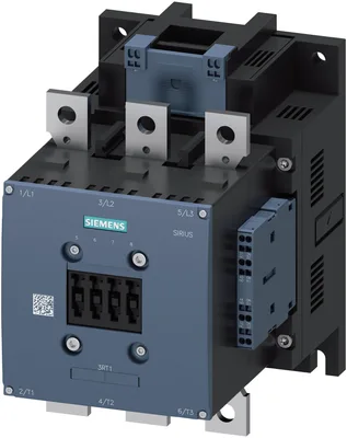
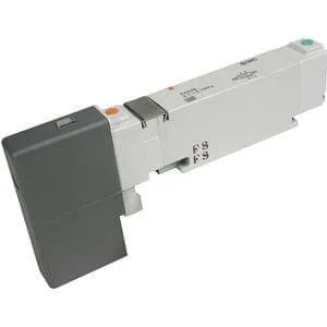
product brand nameSIRIUS
product designationPower contactor
product type designation3RT1
General technical data
size of contactorS10
function module for communicationYok
auxiliary switchVar
at AC in hot operating state54 W
at AC in hot operating state per pole18 W
without load current share typical7,4 W
type of calculation of power loss current-dependentquadratic
of main circuit with degree of pollution 3 rated value1.000 V
of auxiliary circuit with degree of pollution 3 rated value500 V
of main circuit rated value8 kV
of auxiliary circuit rated value6 kV
maximum permissible voltage for protective separation between coil and main contacts according to EN 60947-1690 V
at AC8,5 g / 5 ms, 4,2 g / 10 ms
at DC8,5 g / 5 ms, 4,2 g / 10 ms
at AC13,4 g / 5 ms, 6,5 g / 10 ms
at DC13,4 g / 5 ms, 6,5 g / 10 ms
of contactor typical10.000.000
of the contactor with added electronically optimized auxiliary switch block typical5.000.000
of the contactor with added auxiliary switch block typical10.000.000
reference code according to IEC 81346-2Q
Substance Prohibitance (day/month/year)05/01/2012
SVHC substance nameLead CAS-Yok. 7439-92-1
Net Weight6,152 kg
Ambient conditions
installation altitude at height above sea level maximum2.000 m
during operation-25... +60 °C
during storage-55... +80 °C
relative humidity minimum10 %
relative humidity at 55 °C according to IEC 60068-2-30 maximum95 %
Main circuit
number of poles for main current circuit3
number of NO contacts for main contacts3
number of NC contacts for main contacts0
at AC-3 rated value maximum1.000 V
at AC-3e rated value maximum1.000 V
at AC-1 at 400 V at ambient temperature 40 °C rated value330 A
— up to 690 V at ambient temperature 40 °C rated value330 A
— up to 690 V at ambient temperature 60 °C rated value300 A
— up to 1000 V at ambient temperature 40 °C rated value150 A
— up to 1000 V at ambient temperature 60 °C rated value150 A
— at 400 V rated value265 A
— at 500 V rated value265 A
— at 690 V rated value265 A
— at 1000 V rated value95 A
— at 400 V rated value265 A
— at 500 V rated value265 A
— at 690 V rated value265 A
— at 1000 V rated value95 A
at AC-4 at 400 V rated value230 A
at AC-5a up to 690 V rated value290 A
at AC-5b up to 400 V rated value219 A
— up to 230 V for current peak value n=20 rated value265 A
— up to 400 V for current peak value n=20 rated value265 A
— up to 500 V for current peak value n=20 rated value265 A
— up to 690 V for current peak value n=20 rated value265 A
— up to 1000 V for current peak value n=20 rated value95 A
— up to 230 V for current peak value n=30 rated value184 A
— up to 400 V for current peak value n=30 rated value184 A
— up to 500 V for current peak value n=30 rated value184 A
— up to 690 V for current peak value n=30 rated value184 A
— up to 1000 V for current peak value n=30 rated value95 A
minimum cross-section in main circuit at maximum AC-1 rated value185 mm²
at 400 V rated value117 A
at 690 V rated value105 A
— at 24 V rated value300 A
— at 60 V rated value300 A
— at 110 V rated value33 A
— at 220 V rated value3,8 A
— at 440 V rated value0,9 A
— at 600 V rated value0,6 A
— at 24 V rated value300 A
— at 60 V rated value300 A
— at 110 V rated value300 A
— at 220 V rated value300 A
— at 440 V rated value4 A
— at 600 V rated value2 A
— at 24 V rated value300 A
— at 60 V rated value300 A
— at 110 V rated value300 A
— at 220 V rated value300 A
— at 440 V rated value11 A
— at 600 V rated value5,2 A
— at 24 V rated value300 A
— at 60 V rated value11 A
— at 110 V rated value3 A
— at 220 V rated value0,6 A
— at 440 V rated value0,18 A
— at 600 V rated value0,125 A
— at 24 V rated value300 A
— at 60 V rated value300 A
— at 110 V rated value300 A
— at 220 V rated value2,5 A
— at 440 V rated value0,65 A
— at 600 V rated value0,37 A
— at 24 V rated value300 A
— at 60 V rated value300 A
— at 110 V rated value300 A
— at 220 V rated value300 A
— at 440 V rated value1,4 A
— at 600 V rated value0,75 A
— at 230 V rated value75 kW
— at 400 V rated value132 kW
— at 500 V rated value160 kW
— at 690 V rated value250 kW
— at 1000 V rated value132 kW
— at 230 V rated value75 kW
— at 400 V rated value132 kW
— at 500 V rated value160 kW
— at 690 V rated value250 kW
— at 1000 V rated value132 kW
at 400 V rated value66 kW
at 690 V rated value102 kW
up to 230 V for current peak value n=20 rated value100 kVA
up to 400 V for current peak value n=20 rated value180 kVA
up to 500 V for current peak value n=20 rated value220 kVA
up to 690 V for current peak value n=20 rated value310 kVA
up to 1000 V for current peak value n=20 rated value160 kVA
up to 230 V for current peak value n=30 rated value70 kVA
up to 400 V for current peak value n=30 rated value120 kVA
up to 500 V for current peak value n=30 rated value150 kVA
up to 690 V for current peak value n=30 rated value220 kVA
up to 1000 V for current peak value n=30 rated value160 kVA
limited to 1 s switching at zero current maximum4.880 A; Use minimum cross-section acc. to AC-1 rated value
limited to 5 s switching at zero current maximum4.045 A; Use minimum cross-section acc. to AC-1 rated value
limited to 10 s switching at zero current maximum2.785 A; Use minimum cross-section acc. to AC-1 rated value
limited to 30 s switching at zero current maximum1.664 A; Use minimum cross-section acc. to AC-1 rated value
limited to 60 s switching at zero current maximum1.276 A; Use minimum cross-section acc. to AC-1 rated value
at AC2.000 1/h
at DC2.000 1/h
at AC-1 maximum800 1/h
at AC-2 maximum250 1/h
at AC-3 maximum500 1/h
— maximum500 1/h
at AC-4 maximum130 1/h
Control circuit/ Control
type of voltage of the control supply voltageAC/DC
at 50 Hz rated value220... 240 V
at 60 Hz rated value220... 240 V
control supply voltage at DC rated value220... 240 V
initial value0,8
full-scale value1,1
at 50 Hz0,8... 1,1
at 60 Hz0,8... 1,1
design of the surge suppressorwith varistor
— at 50 Hz490 V·A
— at 60 Hz490 V·A
— at 60 Hz590 V·A
— at 50 Hz590 V·A
at 50 Hz590 V·A
at 60 Hz590 V·A
at 50 Hz0,9
at 60 Hz0,9
at minimum rated control supply voltage at DC6,1 V·A
at maximum rated control supply voltage at DC7,4 V·A
— at 50 Hz5,6 V·A
— at 60 Hz5,6 V·A
— at 50 Hz6,7 V·A
— at 60 Hz6,7 V·A
at 50 Hz0,9
at 60 Hz0,9
closing power of magnet coil at DC650 W
holding power of magnet coil at DC7,4 W
at AC30... 95 ms
at DC30... 95 ms
at AC40... 80 ms
at DC40... 80 ms
arcing time10... 15 ms
control version of the switch operating mechanismStandard A1 - A2
Auxiliary circuit
number of NC contacts for auxiliary contacts instantaneous contact2
number of NO contacts for auxiliary contacts instantaneous contact2
operational current at AC-12 maximum10 A
at 230 V rated value6 A
at 400 V rated value3 A
at 500 V rated value2 A
at 690 V rated value1 A
at 24 V rated value10 A
at 48 V rated value6 A
at 60 V rated value6 A
at 110 V rated value3 A
at 125 V rated value2 A
at 220 V rated value1 A
at 600 V rated value0,15 A
at 24 V rated value10 A
at 48 V rated value2 A
at 60 V rated value2 A
at 110 V rated value1 A
at 125 V rated value0,9 A
at 220 V rated value0,3 A
at 600 V rated value0,1 A
contact reliability of auxiliary contacts1 faulty switching per 100 million (17 V, 1 mA)
UL/CSA ratings
at 480 V rated value240 A
at 600 V rated value242 A
— at 200/208 V rated value75 hp
— at 220/230 V rated value100 hp
— at 460/480 V rated value200 hp
— at 575/600 V rated value250 hp
contact rating of auxiliary contacts according to ULA600 / Q600
Short-circuit protection
design of the miniature circuit breaker for short-circuit protection of the auxiliary circuit up to 230 VC characteristic: 10 A; 0,4 kA
— with type of coordination 1 requiredgG: 500 A (690 V, 100 kA)
— with type of coordination 2 requiredgG: 400 A (690 V, 100 kA), aM: 315 A (690 V, 50 kA), BS88: 400 A (415 V, 50 kA)
for short-circuit protection of the auxiliary switch requiredgG: 10 A (500 V, 1 kA)
Installation/ mounting/ dimensions
mounting positionwith dikey mounting surface +/-90° rotatable, with dikey mounting surface +/- 22,5° tiltable to the front ve back
fastening method side-by-side mountingVar
fastening methodscrew fixing
height210 mm
width145 mm
depth202 mm
— forwards20 mm
— upwards10 mm
— downwards10 mm
— at the side0 mm
— forwards20 mm
— upwards10 mm
— at the side10 mm
— downwards10 mm
— forwards20 mm
— upwards10 mm
— downwards10 mm
— at the side10 mm
Connections/ Terminals
for main current circuitConnection bar
for auxiliary and control circuitspring-loaded terminals
at contactor for auxiliary contactsSpring-type terminals
of magnet coilSpring-loaded terminal
width of connection bar25 mm
thickness of connection bar6 mm
diameter of holes11 mm
number of holes1
for AWG cables for main contacts2/0... 500 kcmil
stranded70... 240 mm²
solid or stranded0,25... 2,5 mm²
finely stranded with core end processing0,25... 1,5 mm²
finely stranded without core end processing0,25... 2,5 mm²
— solid2x (0,25... 2,5 mm²)
— solid or stranded2x (0,25... 2,5 mm²)
— finely stranded with core end processing2x (0,25... 1,5 mm²)
— finely stranded without core end processing2x (0,25... 2,5 mm²)
for AWG cables for auxiliary contacts2x (24... 14)
AWG number as coded connectable conductor cross section for auxiliary contacts24... 14
Safety related data
mirror contact according to IEC 60947-4-1Var
positively driven operation according to IEC 60947-5-1Yok
suitable for safety functionVar
suitability for use safety-related switching OFFVar
service life maximum20 a
test wear-related service life necessaryVar
with low demand rate according to SN 3192040 %
with high demand rate according to SN 3192073 %
B10 value with high demand rate according to SN 319201.000.000
failure rate [FIT] with low demand rate according to SN 31920100 FIT
ISO 13849
device type according to ISO 13849-13
overdimensioning according to ISO 13849-2 necessaryVar
IEC 61508
safety device type according to IEC 61508-2Type A
Electrical Safety
protection class IP on the front according to IEC 60529IP00; IP20 with box terminal/cover
touch protection on the front according to IEC 60529finger-safe, for dikey contact from the front with box terminal/cover
Approvals Certificates
global warming potential [CO2 eq] / during manufacturing31,5 kg
global warming potential [CO2 eq] / during sales2,6 kg
global warming potential [CO2 eq] / during operation521 kg
global warming potential [CO2 eq] / after end of life-7.22 kg
global warming potential [CO2 eq] / total548 kg