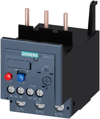
product brand nameSIRIUS
product designationthermal overload relay
product type designation3RU2
General technical data
size of overload relayS2
size of contactor can be combined company-specificS2
power loss [W] for rated value of the current at AC in hot operating state17.1 W
per pole5.7 W
type of calculation of power loss current-dependentquadratic
insulation voltage with degree of pollution 3 at AC rated value690 V
surge voltage resistance rated value6 kV
in networks with ungrounded star point between auxiliary and auxiliary circuit415 V
in networks with grounded star point between auxiliary and auxiliary circuit415 V
in networks with ungrounded star point between main and auxiliary circuit690 V
in networks with grounded star point between main and auxiliary circuit690 V
shock resistance according to IEC 60068-2-278g / 11 ms
with automatic reset typical10 min
with remote-reset10 min
with manual reset10 min
reference code according to IEC 81346-2F
Substance Prohibitance (day/month/year)10/15/2014
Net Weight0.333 kg
Ambient conditions
installation altitude at height above sea level maximum2 000 m
during operation-40 ... +70 °C
during storage-55 ... +80 °C
during transport-55 ... +80 °C
temperature compensation-40 ... +60 °C
relative humidity during operation10 ... 95 %
Main circuit
number of poles for main current circuit3
adjustable current response value current of the current-dependent overload release62 ... 73 A
rated value690 V
at AC-3e rated value maximum690 V
operating frequency rated value50 ... 60 Hz
operational current rated value73 A
operational current at AC-3e at 400 V rated value73 A
— at 400 V rated value37 kW
— at 500 V rated value45 kW
— at 690 V rated value55 kW
— at 400 V rated value37 kW
— at 500 V rated value45 kW
— at 690 V rated value55 kW
Auxiliary circuit
design of the auxiliary switchintegrated
number of NC contacts for auxiliary contacts1
notefor contactor disconnection
number of NO contacts for auxiliary contacts1
notefor message "Tripped"
number of CO contacts for auxiliary contacts0
at 24 V3 A
at 110 V3 A
at 120 V3 A
at 125 V3 A
at 230 V2 A
at 400 V1 A
at 690 V0.75 A
at 24 V2 A
at 60 V0.3 A
at 110 V0.22 A
at 125 V0.22 A
at 220 V0.11 A
design of the miniature circuit breaker for short-circuit protection of the auxiliary switch required6A (SCC less than equal to 0.5 kA; U less than equal to 260V)
contact rating of auxiliary contacts according to ULB600 / R300
Protective and monitoring functions
trip classCLASS 10A
design of the overload releasethermal
UL/CSA ratings
at 480 V rated value73 A
at 600 V rated value73 A
Short-circuit protection
for short-circuit protection of the auxiliary switch requiredfuse gG: 6 A, quick: 10 A
Installation/ mounting/ dimensions
mounting positionfor mounting on contactors: with a vertical mounting plane +/-135° rotatable & +/- 22.5° tiltable, stand-alone installation: with a vertical mounting plane +/-135° rotatable and +/-45° tiltable; for more details see manual
fastening methodContactor mounting
height90 mm
width55 mm
depth105 mm
Connections/ Terminals
product component removable terminal for auxiliary and control circuitNo
for main current circuitscrew-type terminals
for auxiliary and control circuitscrew-type terminals
arrangement of electrical connectors for main current circuitTop and bottom
— solid or stranded2x (1 ... 35 mm²), 1x (1 ... 50 mm²)
— finely stranded with core end processing2x (1 ... 25 mm²), 1x (1 ... 35 mm²)
for AWG cables for main contacts2x (18 ... 2), 1x (18 ... 1)
— solid or stranded2x (0.5 ... 1.5 mm²), 2x (0.75 ... 2.5 mm²)
— finely stranded with core end processing2x (0.5 ... 1.5 mm²), 2x (0.75 ... 2.5 mm²)
for AWG cables for auxiliary contacts2x (20 ... 16), 2x (18 ... 14)
for main contacts with screw-type terminals3 ... 4.5 N·m
for auxiliary contacts with screw-type terminals0.8 ... 1.2 N·m
design of screwdriver shaftDiameter 5 ... 6 mm
size of the screwdriver tipPozidriv PZ 2
for main contactsM6
of the auxiliary and control contactsM3
Safety related data
failure rate [FIT] with low demand rate according to SN 3192050 FIT
MTTF with high demand rate2 280 a
IEC 61508
for proof test interval or service life according to IEC 6150820 a
Electrical Safety
protection class IP on the front according to IEC 60529IP20
touch protection on the front according to IEC 60529finger-safe, for vertical contact from the front
Display
display version for switching statusSlide switch
Approvals Certificates
global warming potential [CO2 eq] / during manufacturing1.8 kg
global warming potential [CO2 eq] / during sales0.0825 kg
global warming potential [CO2 eq] / during operation107 kg
global warming potential [CO2 eq] / after end of life-0.0625 kg
global warming potential [CO2 eq] / total108 kg