Genel bilgiler
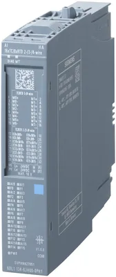
Ürün tipi tanımıAI 16 x TC/8 x RTD 2/3/4-wire HA
Firmware sürümüV1.1
FW update possibleVar
Usable terminal blocktype H1, M1, N0, H0, M0 (for details see the system manual)
Color code for module-specific color-coded labelCC00
Product function
I&M dataVar; I&M0 to I&M3
Mühendislik aracı
STEP 7 TIA Portal configurable/integrated from versionV16
STEP 7 configurable/integrated from versionV5.6
PCS 7 configurable/integrated from versionV9.0
PCS neo can be configured/integrated from versionV3.0
PROFINET from GSD version/GSD revisionGSDML V2.3
Redundancy
Redundancy capabilityVar; With TB type M1
CiR - Configuration in RUN
Reparameterization possible in RUNVar
Besleme gerilimi
Nominal değer (DC)24 V
İzin verilen aralık, alt sınır (DC)19,2 V
İzin verilen aralık, üst sınır (DC)28,8 V
Ters polarite korumasıVar
Giriş akımı
Akım tüketimi (nominal değer)75 mA
Akım tüketimi, maks.100 mA
Güç kaybı
Güç kaybı, tipik1,8 W
Address space per module
Address space per module, max.64 bayt; + 2 bytes for QI information
Analog girişler
For voltage measurement16
For resistance/resistance thermometer measurement8
For thermocouple measurement16
permissible input voltage for voltage input (destruction limit), max.5 V
Constant measurement current for resistance-type transmitter, typ.2 mA
Technical unit for temperature measurement adjustableVar; °C/°F/K
Giriş aralıkları (nominal değerler), gerilim
-1 V to +1 VVar; 16 bit incl. sign
— Input resistance (-1 V to +1 V)1 MΩ
-250 mV to +250 mVVar; 16 bit incl. sign
— Input resistance (-250 mV to +250 mV)1 MΩ
-50 mV to +50 mVVar; 16 bit incl. sign
— Input resistance (-50 mV to +50 mV)1 MΩ
-80 mV to +80 mVVar; 16 bit incl. sign
— Input resistance (-80 mV to +80 mV)1 MΩ
Input ranges (rated values), thermocouples
type BVar; 16 bit incl. sign
— Input resistance (Type B)1 MΩ
type CVar; 16 bit incl. sign
— Input resistance (Type C)1 MΩ
Type EVar; 16 bit incl. sign
— Input resistance (Type E)1 MΩ
Type JVar; 16 bit incl. sign
— Input resistance (type J)1 MΩ
Type KVar; 16 bit incl. sign
— Input resistance (Type K)1 MΩ
Type LVar; 16 bit incl. sign
— Input resistance (Type L)1 MΩ
Type NVar; 16 bit incl. sign
— Input resistance (Type N)1 MΩ
Type RVar; 16 bit incl. sign
— Input resistance (Type R)1 MΩ
Type SVar; 16 bit incl. sign
— Input resistance (Type S)1 MΩ
Type TVar; 16 bit incl. sign
— Input resistance (Type T)1 MΩ
Type UVar; 16 bit incl. sign
— Input resistance (Type U)1 MΩ
Type TXK/TXK(L) to GOSTVar; 16 bit incl. sign
— Input resistance (Type TXK/TXK(L) to GOST)1 MΩ
Input ranges (rated values), resistance thermometer
Cu 10Var; 16 bit incl. sign
— Input resistance (Cu 10)1 MΩ
Ni 100Var; 16 bit incl. sign
— Input resistance (Ni 100)1 MΩ
Ni 1000Var; 16 bit incl. sign
— Input resistance (Ni 1000)1 MΩ
LG-Ni 1000Var; 16 bit incl. sign
Ni 120Var; 16 bit incl. sign
— Input resistance (Ni 120)1 MΩ
Ni 200Var; 16 bit incl. sign
— Input resistance (Ni 200)1 MΩ
Ni 500Var; 16 bit incl. sign
— Input resistance (Ni 500)1 MΩ
Pt 100Var; 16 bit incl. sign
— Input resistance (Pt 100)1 MΩ
Pt 1000Var; 16 bit incl. sign
— Input resistance (Pt 1000)1 MΩ
Pt 200Var; 16 bit incl. sign
— Input resistance (Pt 200)1 MΩ
Pt 500Var; 16 bit incl. sign
— Input resistance (Pt 500)1 MΩ
Input ranges (rated values), resistors
0 to 150 ohmsVar; 15 bit
— Input resistance (0 to 150 ohms)1 MΩ
0 to 300 ohmsVar; 15 bit
— Input resistance (0 to 300 ohms)1 MΩ
0 to 600 ohmsVar; 15 bit
— Input resistance (0 to 600 ohms)1 MΩ
0 to 3000 ohmsVar; 15 bit
— Input resistance (0 to 3000 ohms)1 MΩ
0 to 6000 ohmsVar; 15 bit
— Input resistance (0 to 6000 ohms)1 MΩ
PTCVar; 15 bit
— Input resistance (PTC)1 MΩ
Temperature compensation
— ParametrelenebilirVar
— external temperature compensation via RTDVar
— Reference channel of the moduleVar
— internal comparison pointVar; with terminal block H1 ve M1
— Reference channel of the groupVar
— Number of reference channel groups4
— fixed reference temperatureVar
Kablo uzunluğu
Ekranlı, maks.200 m; Measurement ranges for thermocouples / voltages: shielded cable length maks. 600 m, loop resistance max 8 kOhm; measuring ranges RTD: shielded cable length maks. 600 m, cable resistance (single) maks. 75 ohms
Analog value generation for the inputs
Measurement principleintegrating (Sigma-Delta)
Kanal başına entegrasyon/dönüşüm süresi ve çözünürlük
Aşım dahil çözünürlük (işaret biti dahil), maks.16 bit
Entegrasyon süresi, parametrelenebilirVar; Channel-by-channel, results from the selected interference frequency suppression
Interference voltage suppression for interference frequency f1 in Hz16,6 / 50 / 60 Hz, channel-by-channel
Dönüşüm süresi (kanal başına)60 ms; 180 / 50 ms, results from the selected interference frequency suppression
Smoothing of measured values
ParameterizableVar; yok, weak, medium, strong, channel-by-channel
Errors/accuracies
Linearity error (relative to input range), (+/-)0,01 %; ±0,1 % for resistance thermometers ve resistance
Temperature error (relative to input range), (+/-)0,0009 %/K; ±0,005 % / K thermocouple
Crosstalk between the inputs, min.50 dB
Repeat accuracy in steady state at 25 °C (relative to input range), (+/-)0,05 %
Operational error limit in overall temperature range
Voltage, relative to input range, (+/-)0,1 %
Resistance, relative to input range, (+/-)0,1 %
Basic error limit (operational limit at 25 °C)
Voltage, relative to input range, (+/-)0,05 %
Resistance, relative to input range, (+/-)0,05 %
Interference voltage suppression for f = n x (f1 +/- 1 %), f1 = interference frequency
Series mode interference (peak value of interference < rated value of input range), min.70 dB
Common mode voltage, max.60 V
Common mode interference, min.90 dB
Interrupts/diagnostics/status information
Diagnostics functionVar
Alarms
Diagnostic alarmVar
Limit value alarmVar; two upper ve two lower limit values in her biri case
Diagnoses
Monitoring the supply voltageVar
Wire breakVar; channel by channel
Overflow/UnderflowVar; channel by channel
Tanılama gösterge LED’i
MAINT LED’iVar; Yellow LED
Monitoring of the supply voltage (PWR-LED)Var; green PWR LED
Channel status displayVar; green LED
for channel diagnosticsVar; red LED
for module diagnosticsVar; green/red DIAG LED
Potential separation channels
Kanallar arasıYok
between the channels and backplane busVar
Between the channels and load voltage L+Var
Permissible potential difference
between the inputs (UCM)75 V DC/60 V AC
Isolation
Isolation tested with1.500 V DC/1 min, type test
Çalışma ortam sıcaklığı
Yatay montaj, min.-40 °C
Yatay montaj, maks.70 °C
Dikey montaj, min.-40 °C
Dikey montaj, maks.60 °C
Ölçüler
Genişlik22,5 mm
Yükseklik115 mm
Derinlik138 mm
Ağırlık
Ağırlık, yaklaşık150 g