Genel bilgiler
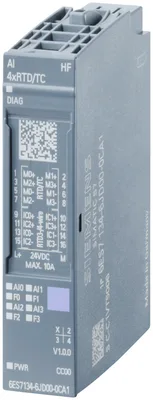
Ürün tipi tanımıAI 4xRTD/TC 2-/3-/4-wire HF
FW update possibleVar
based on6ES7134-6JD00-0CA1
usable BaseUnitsBU type A0, A1
Color code for module-specific color-coded labelCC00
Product function
I&M dataVar; I&M0 to I&M3
Isochronous modeYok
Adjustment of measuring rangeVar
Mühendislik aracı
STEP 7 TIA Portal configurable/integrated from versionsee entry ID: 109746275
Operating mode
OversamplingYok
MSIYok
CiR - Configuration in RUN
Reparameterization possible in RUNVar
Calibration possible in RUNVar
Besleme gerilimi
Nominal değer (DC)24 V
İzin verilen aralık, alt sınır (DC)19,2 V
İzin verilen aralık, üst sınır (DC)28,8 V
Ters polarite korumasıVar
Giriş akımı
Akım tüketimi (nominal değer)30 mA
Akım tüketimi, maks.32 mA
Güç kaybı
Güç kaybı, tipik0,75 W
Address space per module
Address space per module, max.8 bayt; + 1 bayt for QI information
Donanım yapılandırması
Mechanical coding elementVar
Type of mechanical coding elementType A
Analog girişler
Analog giriş sayısı4
permissible input voltage for voltage input (destruction limit), max.30 V
Constant measurement current for resistance-type transmitter, typ.2 mA
Cycle time (all channels), min.Sum of the basic conversion times ve additional processing times (depending on the parameterization of the active channels); for line compensation in case of a three-wire connection, an additional cycle is necessary
Technical unit for temperature measurement adjustableVar; °C/°F/K
Giriş aralıkları (nominal değerler), gerilim
-1 V to +1 VVar; 16 bit incl. sign
— Input resistance (-1 V to +1 V)1 MΩ
-250 mV to +250 mVVar; 16 bit incl. sign
— Input resistance (-250 mV to +250 mV)1 MΩ
-50 mV to +50 mVVar; 16 bit incl. sign
— Input resistance (-50 mV to +50 mV)1 MΩ
-80 mV to +80 mVVar; 16 bit incl. sign
— Input resistance (-80 mV to +80 mV)1 MΩ
Input ranges (rated values), thermocouples
type BVar; 16 bit incl. sign
— Input resistance (Type B)1 MΩ
type CVar; 16 bit incl. sign
— Input resistance (Type C)1 MΩ
Type EVar; 16 bit incl. sign
— Input resistance (Type E)1 MΩ
Type JVar; 16 bit incl. sign
— Input resistance (type J)1 MΩ
Type KVar; 16 bit incl. sign
— Input resistance (Type K)1 MΩ
Type LVar; 16 bit incl. sign
— Input resistance (Type L)1 MΩ
Type NVar; 16 bit incl. sign
— Input resistance (Type N)1 MΩ
Type RVar; 16 bit incl. sign
— Input resistance (Type R)1 MΩ
Type SVar; 16 bit incl. sign
— Input resistance (Type S)1 MΩ
Type TVar; 16 bit incl. sign
— Input resistance (Type T)1 MΩ
Type UVar; 16 bit incl. sign
— Input resistance (Type U)1 MΩ
Type TXK/TXK(L) to GOSTVar; 16 bit incl. sign
— Input resistance (Type TXK/TXK(L) to GOST)1 MΩ
Input ranges (rated values), resistance thermometer
Cu 10Var; 16 bit incl. sign
— Input resistance (Cu 10)1 MΩ
Ni 100Var; 16 bit incl. sign
— Input resistance (Ni 100)1 MΩ
Ni 1000Var; 16 bit incl. sign
— Input resistance (Ni 1000)1 MΩ
LG-Ni 1000Var; 16 bit incl. sign
— Input resistance (LG-Ni 1000)1 MΩ
Ni 120Var; 16 bit incl. sign
— Input resistance (Ni 120)1 MΩ
Ni 200Var; 16 bit incl. sign
— Input resistance (Ni 200)1 MΩ
Ni 500Var; 16 bit incl. sign
— Input resistance (Ni 500)1 MΩ
Pt 100Var; 16 bit incl. sign
— Input resistance (Pt 100)1 MΩ
Pt 1000Var; 16 bit incl. sign
— Input resistance (Pt 1000)1 MΩ
Pt 200Var; 16 bit incl. sign
— Input resistance (Pt 200)1 MΩ
Pt 500Var; 16 bit incl. sign
— Input resistance (Pt 500)1 MΩ
Input ranges (rated values), resistors
0 to 150 ohmsVar; 15 bit
— Input resistance (0 to 150 ohms)1 MΩ
0 to 300 ohmsVar; 15 bit
— Input resistance (0 to 300 ohms)1 MΩ
0 to 600 ohmsVar; 15 bit
— Input resistance (0 to 600 ohms)1 MΩ
0 to 3000 ohmsVar; 15 bit
— Input resistance (0 to 3000 ohms)1 MΩ
0 to 6000 ohmsVar; 15 bit
— Input resistance (0 to 6000 ohms)1 MΩ
PTCVar; 15 bit
— Input resistance (PTC)1 MΩ
Temperature compensation
— ParametrelenebilirVar
— Reference channel of the moduleVar
— internal comparison pointVar; with BaseUnit type A1
— Reference channel of the groupVar
— Number of reference channel groups4; Group 0 to 3
— fixed reference temperatureVar
Kablo uzunluğu
Ekranlı, maks.200 m; 50 m with thermocouples
Analog value generation for the inputs
Measurement principleintegrating (Sigma-Delta)
Kanal başına entegrasyon/dönüşüm süresi ve çözünürlük
Aşım dahil çözünürlük (işaret biti dahil), maks.16 bit
Entegrasyon süresi, parametrelenebilirVar
— additional processing time for wire-break check2 ms; In the ranges resistance thermometers, resistors ve thermocouples
— additional power line wire-break check2 ms; for 3/4 wire transducer (resistance thermometer ve resistor)
Interference voltage suppression for interference frequency f1 in Hz16,6 / 50 / 60 Hz
Dönüşüm süresi (kanal başına)180 / 60 / 50 / (67,5 / 22,5 / 18,75) ms
Smoothing of measured values
Number of smoothing levels4; Yok; 4/8/16 times
ParameterizableVar
Connection of signal encoders
for voltage measurementVar
for resistance measurement with two-wire connectionVar
for resistance measurement with three-wire connectionVar
for resistance measurement with four-wire connectionVar
Errors/accuracies
Linearity error (relative to input range), (+/-)0,01 %; ±0,1 % for resistance thermometers ve resistance
Temperature error (relative to input range), (+/-)0,0009 %/K; ±0,005 % / K thermocouple
Crosstalk between the inputs, min.-50 dB
Repeat accuracy in steady state at 25 °C (relative to input range), (+/-)0,05 %
Operational error limit in overall temperature range
Voltage, relative to input range, (+/-)0,2 %
Resistance, relative to input range, (+/-)0,2 %
Basic error limit (operational limit at 25 °C)
Voltage, relative to input range, (+/-)0,05 %
Resistance, relative to input range, (+/-)0,05 %
Interference voltage suppression for f = n x (f1 +/- 1 %), f1 = interference frequency
Series mode interference (peak value of interference < rated value of input range), min.70 dB
Common mode voltage, max.10 V
Common mode interference, min.90 dB
Interrupts/diagnostics/status information
Diagnostics functionVar
Alarms
Diagnostic alarmVar
Limit value alarmVar; two upper ve two lower limit values in her biri case
Diagnoses
Monitoring the supply voltageVar
Wire breakVar; channel by channel
Group errorVar
Overflow/UnderflowVar; channel by channel
Tanılama gösterge LED’i
Monitoring of the supply voltage (PWR-LED)Var; green PWR LED
Channel status displayVar; green LED
for channel diagnosticsVar; red LED
for module diagnosticsVar; green/red DIAG LED
Potential separation channels
Kanallar arasıYok
between the channels and backplane busVar
between the channels and the power supply of the electronicsVar
Permissible potential difference
between the inputs (UCM)10 V DC
Isolation
Isolation tested with750 V DC (type test) ve according to EN 50155 (routine test)
Railway application
EN 50121-3-2Var; EMC for rail vehicles
EN 50121-4Var; EMC for signal ve telecommunications systems
EN 50121-5Var; EMC for fixed installations ve railway power supply equipment
EN 50124-1Var; Railway applications - overvoltage category OV2; pollution degree PD2; rated surge voltage UNi = 0,5 kV; UNm = 24 V DC
EN 50125-1Var; Rail vehicles - see ambient conditions
EN 50125-2Var; Stationary electrical equipment - see ambient conditions
EN 50125-3Var; Signal ve telecommunications systems - see ambient conditions; vibrations ve shocks: Application point outside of tracks (1 m to 3 m away from track)
EN 50155Var; Rail vehicles - temperature class OT2, ST1/ST2, yatay mounting position
EN 61373Var; Rail vehicles - vibrations ve shocks: Category 1 Class A/B
Fire protection acc. to EN 45545-2Var; Rail vehicles - verification talep üzerine
Çalışma ortam sıcaklığı
Yatay montaj, min.-40 °C; = Tmin (incl. condensation/frost)
Yatay montaj, maks.60 °C; = Tmax; +70 °C for 10 min (OT2, ST1/ST2 acc. to EN 50155); +70 °C continuously with spacing modules (6AG2193-6BN00-4BA0) veya configured slots to the left ve right of the module (OT4, ST0 acc. to EN 50155)
Dikey montaj, min.-40 °C; = Tmin
Dikey montaj, maks.50 °C; = Tmax
Deniz seviyesine göre çalışma yüksekliği
Installation altitude above sea level, max.2.000 m
Ambient air temperature-barometric pressure-altitudeTmin... Tmax 1.140 hPa... 795 hPa (-1 000 m... +2.000 m)
Bağıl nem
With condensation, tested in accordance with IEC 60068-2-38, max.100 %; RH incl. condensation / frost (no commissioning in bedewed state), yatay installation
Coolants and lubricants
— Resistant to commercially available coolants and lubricantsVar; Incl. diesel ve oil droplets in the air
Use in stationary industrial systems
— to biologically active substances according to EN 60721-3-3Var; Class 3B2 mold, fungus ve dry rot spores (with the exception of fauna); Class 3B3 talep üzerine
— to chemically active substances according to EN 60721-3-3Var; Class 3C4 (RH < 75 %) incl. salt spray acc. to EN 60068-2-52 (severity degree 3); *
— to mechanically active substances according to EN 60721-3-3Var; Class 3S4 incl. sand, dust, *
— Against mechanical environmental conditions acc. to EN 60721-3-3Var; Class 3M8 using the SIPLUS Mounting Kit ET 200SP (6AG1193-6AA00-0AA0)
Use on land craft, rail vehicles and special-purpose vehicles
— to biologically active substances according to EN 60721-3-5Var; Class 5B2 mold, fungus ve dry rot spores (with the exception of fauna); Class 5B3 talep üzerine
— to chemically active substances according to EN 60721-3-5Var; Class 5C3 (RH < 75 %) incl. salt spray acc. to EN 60068-2-52 (severity degree 3); *
— to mechanically active substances according to EN 60721-3-5Var; Class 5S3 incl. sand, dust; *
— Against mechanical environmental conditions acc. to EN 60721-3-5Var; Class 5M2 using the SIPLUS Mounting Kit ET 200SP (6AG1193-6AA00-0AA0)
Usage in industrial process technology
— Against chemically active substances acc. to EN 60654-4Var; Class 3 (excluding trichlorethylene)
— Environmental conditions for process, measuring and control systems acc. to ANSI/ISA-71.04Var; Level GX group A/B (excluding trichlorethylene; harmful gas concentrations up to the limits of EN 60721-3-3 class 3C4 permissible); level LC3 (salt spray) ve level LB3 (oil)
Remark
— Note regarding classification of environmental conditions acc. to EN 60721, EN 60654-4 and ANSI/ISA-71.04* The supplied plug covers must remain in place over the unused interfaces during operation!
Conformal coating
Coatings for printed circuit board assemblies acc. to EN 61086Var; Class 2 for high reliability
Protection against fouling acc. to EN 60664-3Var; Type 1 protection
Electronic equipment on rolling stock acc. to EN 50155Var; Class PC2 protective coating acc. to EN 50155:2017
Military testing according to MIL-I-46058C, Amendment 7Var; Discoloration of coating possible during service life
Qualification and Performance of Electrical Insulating Compound for Printed Board Assemblies according to IPC-CC-830AVar; Conformal coating, Class A
Ölçüler
Genişlik15 mm
Yükseklik73 mm
Derinlik58 mm
Other
Note:for use in railway applications, also observe the product information "SIPLUS extreme RAIL" A5E37661960A, Online Support article 109736776