Genel bilgiler
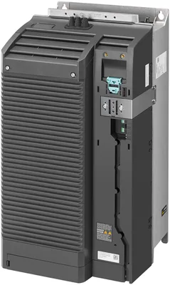
Ürün tipi tanımıPM240-2
Product versionFSE 45 kW
Design of the converterFSE
based on6SL3210-1PE28-8UL0
Protection function
Undervoltage protectionVar
Overvoltage protectionVar
Overload protectionVar
Ground-fault protectionVar
short-circuit protectionVar
Stall protectionVar
With blocked rotorVar
Temperature monitor for motorVar
Temperature monitor for converterVar
Parameter lockingVar
Giriş gerilimi
Type of input voltageAC
Mains filter
MevcutYok
Giriş akımı
Input current with low overload86 A
Input current with high overload78 A
Çıkış gerilimi
Output voltage in relation to input voltage, min.0 %
Output voltage in relation to input voltage, max.95 %
Pulse frequency4 kHz
Çıkış akımı
Output current, max.150 A
Output current without overload90 A
Output current with low overload90 A
Output current with high overload75 A
Güç kaybı
Power loss, max.1,194 kW
Power loss of the CDM in standby mode32 W
Power loss of the CDM at the operating point (0/25)406 W
Power loss of the CDM at the operating point (0/50)543 W
Power loss of the CDM at the operating point (0/100)955 W
Power loss of the CDM at the operating point (50/25)424 W
Power loss of the CDM at the operating point (50/50)599 W
Power loss of the CDM at the operating point (50/100)1.092 W
Power loss of the CDM at the operating point (90/50)674 W
Power loss of the CDM at the operating point (90/100)1.317 W
Relative power loss of the CDM at the operating point (0/25)0,65 %
Relative power loss of the CDM at the operating point (0/50)0,87 %
Relative power loss of the CDM at the operating point (0/100)1,53 %
Relative power loss of the CDM at the operating point (50/25)0,68 %
Relative power loss of the CDM at the operating point (50/50)0,96 %
Relative power loss of the CDM at the operating point (50/100)1,75 %
Relative power loss of the CDM at the operating point (90/50)1,08 %
Relative power loss of the CDM at the operating point (90/100)2,11 %
Ratio of converter losses / reference converter losses at the operating point (90/100)55,58
IE class of the CDMIE2
Power electronics
emitted active power with low overload45 kW
emitted active power with high overload37 kW
active power output with low overload [hp]60 hp
active power output with high overload [hp]50 hp
apparent power output62,4 kVA
Efficiency0,98
Type of duty cycle duration with low overload1.1x rated output current (i.e. 110 % overload) for 57 s with a cycle time of 300 s; 1.5x rated output current (i.e. 150 % overload) for 3 s with a cycle time of 300 s
Type of duty cycle duration with high overload1.5x output current rating (i.e. 150 % overload) for 57 s with a cycle time of 300 s; 2x output current rating (i.e. 200 % overload) for 3 s with a cycle time of 300 s
Cooling methodInternal air cooling
Cooling air flow0,083 m³/s
Short-time withstand current (SCCR) of the entire control cabinet in accordance with UL 508A65 kA
Isolation
Degree of pollution2 according to EN 61800-5-1
Koruma derecesi ve sınıfı
IP koruma sınıfıIP20
Equipment protection class according to EN 61800-5-1Class I (with protective bonding circuit) ve Class III (PELV)
Touch protection according to EN 61800-5-1Assuming use as prescribed
Standartlar, onaylar, sertifikalar
Certificate of suitabilityCE / TÜV
Standard for EMC according to EN 61800-3the EMC product standard EN 61800-3 does not apply directly to a frequency inverter but to a PDS (Power Drive System), which comprises the complete circuitry, motor ve cables in addition to the inverter
Çalışma ortam sıcaklığı
min.-20 °C; = Tmin
maks.50 °C; = Tmax
Depolama/taşıma ortam sıcaklığı
Storage, min.-25 °C
Storage, max.55 °C
Storage, min. [°F]-13 °F
Storage, max. [°F]131 °F; Class 1K3 acc. to EN 60721-3-1
Transportation, min.-40 °C
Transportation, max.70 °C
Transport, min. [°F]-40 °F
Transport, max. [°F]158 °F; Class 2K3 according to EN 60721-3-2
Deniz seviyesine göre çalışma yüksekliği
Installation altitude above sea level without derating, max.1.000 m
Bağıl nem
Çalışma, maks.98 %
Condensation permissibleYok
Titreşim
Vibration frequency with constant acceleration during operation according to EN 60068-2-6, min.10 Hz
Vibration frequency with constant acceleration during operation according to EN 60068-2-6, max.200 Hz; Constant acceleration = 9,81 m/s² (1 g)
Vibration frequency with constant deflection during operation according to EN 60068-2-6, min.13 Hz
Vibration frequency with constant deflection during operation according to EN 60068-2-6, max.58 Hz; Constant deflection 0,075 mm
Oscillation frequency during transport in accordance with EN 60721-3-2Class 2M3
Şok testi
Shock load during operation(15x g)/11 ms
Shock acceleration during operation according to EN 60068-2-27147 m/s²
Shock acceleration during transport according to EN 60721-3-2Class 2M3
Use in stationary industrial systems
— to biologically active substances according to EN 60721-3-3Var; Class 3B2 mold, fungus ve dry rot spores (with the exception of fauna); Class 3B3 talep üzerine
— to chemically active substances according to EN 60721-3-3Var; Class 3C4 (RH < 75 %) incl. salt spray acc. to EN 60068-2-52 (severity degree 3); *
— to mechanically active substances according to EN 60721-3-3Yok
Usage in industrial process technology
— Against chemically active substances acc. to EN 60654-4Var; Class 3 (excluding trichlorethylene)
— Environmental conditions for process, measuring and control systems acc. to ANSI/ISA-71.04Var; Level GX group A/B (excluding trichlorethylene; harmful gas concentrations up to the limits of EN 60721-3-3 class 3C4 permissible); level LC3 (salt spray) ve level LB3 (oil)
Remark
— Note regarding classification of environmental conditions acc. to EN 60721, EN 60654-4 and ANSI/ISA-71.04* The supplied plug covers must remain in place over the unused interfaces during operation!
Conformal coating
Coatings for printed circuit board assemblies acc. to EN 61086Var; Class 2 for high reliability
Military testing according to MIL-I-46058C, Amendment 7Var; Discoloration of coating possible during service life
Qualification and Performance of Electrical Insulating Compound for Printed Board Assemblies according to IPC-CC-830AVar; Conformal coating, Class A
Cables
Cable length for motor, shielded, max.200 m
Cable length for braking resistor, max.10 m
Connection method
Design of electrical connection of motorScrew terminals
connectable cable cross-section for motor supply line, min.25 mm²
connectable cable cross-section for motor supply line, max.70 mm²
Connectable conductor cross-section for AWG cables, min.4
Type of electrical connection for mains supply lineScrew terminals
connectable cable cross-section for mains supply line, min.25 mm²
connectable cable cross-section for mains supply line, max.70 mm²
Connectable conductor cross-section for AWG cables, min.4
Type of electrical connection for supply cable to braking resistorScrew terminals
Connectable cable cross-section for supply cable to braking resistor, min.10 mm²
Connectable cable cross-section for supply cable to braking resistor, max.35 mm²
Connectable conductor cross-section for AWG cables, min.8
Connectable conductor cross-section for AWG cables, max.2
Design of electrical connection for the PE conductorScrew terminals
Ölçüler
Genişlik275 mm
Yükseklik551 mm
Derinlik237 mm
Ağırlık
Weight (without packaging)26 kg
Other
Sound pressure level (1 m), max.70,6 dB
Brake designDC braking, compound braking, resistance braking with dahili brake chopper (for size FSGX optional)