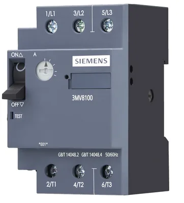
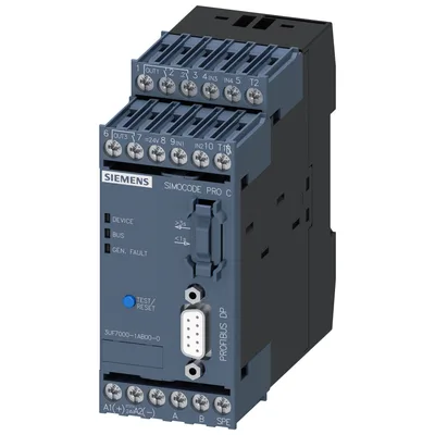
product brand nameSIMOCODE
product designationMotor management system
design of the productbasic unit 1
product type designationpro C
General technical data
certificate of suitabilityCE / UL / CSA / CCC / C-Tick (RCM) / GOST / NOM / ATEX / NEPSI / ABS / DNV / GL / LRS / RoHS
current measurementYok
voltage measurementYok
active power measurementYok
energy measurementYok
frequency measurementYok
bus communicationVar
data acquisition functionVar
diagnostics functionVar
password protectionVar
test functionVar
maintenance functionVar
MRRT redundancy procedureYok
input for thermistor connectionVar
digital inputVar
input for analog temperature sensorsYok
input for ground fault detectionYok
relay outputVar
temperature monitoring moduleYok
current measuring moduleVar
current/voltage measuring moduleYok
fail-safe digital I/O moduleYok
ground-fault monitoring moduleYok
decoupling moduleYok
analog I/O moduleYok
digital I/O module with monostable outputsYok
digital I/O module with bistable outputsYok
control unit with displayYok
control unitVar
consumed active power2,3 W
insulation voltage with degree of pollution 3 at AC rated value300 V
surge voltage resistance rated value4.000 V
according to IEC 60068-2-2715 g / 11 ms
vibration resistance1 … 6 Hz / 15 mm; 6 … 500 Hz / 2 g
at 24 V6 A
at 120 V6 A
at 230 V3 A
at 24 V2 A
at 60 V0,55 A
at 125 V0,25 A
mechanical service life (operating cycles) typical10.000.000
electrical endurance (operating cycles) typical100.000
buffering time in the event of power failure0,05 s
reference code according to IEC 81346-2F
at 50 °C6 A
at 60 °C5 A
type of input characteristicType 1 in accordance with EN 61131-2
Substance Prohibitance (day/month/year)05/01/2012
SVHC substance nameLead CAS-Yok. 7439-92-1 Lead monoxide (lead oxide) CAS-Yok. 1317-36-8 2-methyl-1-(4-methylthiophenyl)-2-morpholinopropan-1-one CAS-Yok. 71868-10-5 Melamine CAS-Yok. 108-78-1
Net Weight281,5 g
Electromagnetic compatibility
EMC emitted interference according to IEC 60947-1class A
EMC immunity according to IEC 60947-1corresponds to degree of severity 3
due to burst according to IEC 61000-4-42 kV (power ports) / 1 kV (signal ports)
due to conductor-earth surge according to IEC 61000-4-52 kV
due to conductor-conductor surge according to IEC 61000-4-51 kV
due to high-frequency radiation according to IEC 61000-4-610 V
field-based interference according to IEC 61000-4-310 V/m
electrostatic discharge according to IEC 61000-4-26 kV contact discharge / 8 kV air discharge
conducted HF interference emissions according to CISPR11corresponds to degree of severity A
field-bound HF interference emission according to CISPR11corresponds to degree of severity A
Inputs/ Outputs
parameterizable inputsVar
parameterizable outputsVar
number of inputs4
for thermistor connection1
number of digital inputs with a common reference potential4
type 1 acc. to IEC 61131Var
rated value24 V
number of outputs3
number of semiconductor outputs0
number of outputs as contact-affected switching element3
switching behaviormonostable
number of relay outputs3
type of relay outputsMonostable
wire length for digital signals maximum300 m
with conductor cross-section = 0.5 mm² maximum50 m
with conductor cross-section = 1.5 mm² maximum150 m
with conductor cross-section = 2.5 mm² maximum250 m
Protective and monitoring functions
asymmetry detectionVar
blocking current evaluationVar
power factor monitoringYok
ground fault detectionVar
ground-fault monitoringYok
phase failure detectionVar
phase sequence recognitionYok
voltage detectionYok
monitoring of number of start operationsVar
overvoltage detectionYok
overcurrent detection 1 phaseVar
undervoltage detectionYok
undercurrent detection 1 phaseVar
active power monitoringYok
current detectionVar
overload protectionVar
evaluation of thermistor motor protectionVar
total cold resistance number of sensors in series maximum1,5 kΩ
response value of thermoresistor3.400... 3.800 Ω
of the short-circuit control9 Ω
release value of thermoresistor1.500... 1.650 Ω
Motor control functions
parameterizable overload relayVar
circuit breaker controlVar
direct startVar
reverse startingVar
star-delta circuitYok
star-delta reversing circuitYok
Dahlander circuitYok
Dahlander reversing circuitYok
pole-changing switch circuitYok
pole-changing switch reversing circuitYok
slide controlYok
valve controlYok
Communication/ Protocol
PROFIBUS DP protocolVar
PROFINET IO protocolYok
PROFIsafe protocolYok
Modbus RTUYok
EtherNet/IPYok
OPC UA sunucusuYok
LLDPYok
Address Resolution Protocol (ARP)Yok
SNMPYok
HTTPSYok
NTPYok
Media Redundancy Protocol (MRP)Yok
web serverYok
shared deviceYok
at the Ethernet interface AutocrossoverYok
at the Ethernet interface AutonegotiationYok
at the Ethernet interface AutosensingYok
is supported Device Level Ring (DLR)Yok
is supported PROFINET system redundancy (S2)Yok
supports PROFIenergy measured valuesYok
supports PROFIenergy shutdownYok
transfer rate maximum12 Mbit/s
I&M0 - device-specific informationVar
I&M1 - higher level designation/location designationVar
I&M2 - installation dateVar
I&M3 - commentVar
type of electrical connection of the communication interface9-pin SUB-D socket (12 Mbit) / screw terminal (1,5 Mbit)
Installation/ mounting/ dimensions
mounting positionany
fastening methodscrew ve snap-on mounting
height111 mm
width45 mm
depth95 mm
top40 mm
bottom40 mm
left0 mm
right0 mm
Connections/ Terminals
product component removable terminal for auxiliary and control circuitVar
for auxiliary and control circuitscrew-type terminals
solid1x (0,5... 4.0mm²), 2x (0,5... 2,5 mm²)
finely stranded with core end processing1x (0,5... 2,5 mm²), 2x (0,5... 1,5 mm²)
for AWG cables solid1x (20... 12), 2x (20... 14)
for AWG cables stranded1x (20... 14), 2x (20... 16)
tightening torque with screw-type terminals0,8... 1,2 N·m
tightening torque [lbf·in] with screw-type terminals7... 10,3 lbf·in
type of connectable conductor cross-sections for PROFIBUS wire2x 0,34 mm², AWG 22
Ambient conditions
installation altitude at height above sea level maximum2.000 m
during operation-25... +60 °C
during storage-40... +80 °C
during transport-40... +80 °C
during operation according to IEC 607213K6 (no formation of ice, no condensation, relative humidity 10... 95%), 3C3 (no salt mist), 3S2 (sand must not get into the devices), 3M6
during storage according to IEC 607211K6 (no condensation, relative humidity 10... 95%), 1C2 (no salt mist), 1S2 (sand must not get into the devices), 1M4
during transport according to IEC 607212K2, 2C1, 2S1, 2M2
during operation5... 95 %
contact rating of auxiliary contacts according to ULB300 / R300
Short-circuit protection
design of short-circuit protection per outputFuse links: gG 6 A, quick-response 10 A (IEC 60947-5-1), miniature circuit-breaker C char.: 1,6 A (IEC 60947-5-1) veya 6 A (I_K < 500 A)
Electrical Safety
touch protection against electrical shockfinger-safe
ATEX
according to ATEX directive 2014/34/EUBVS 06 ATEX F001
acc. to Equipment and Protective System Intended for Use in Potentially Explosive Atmospheres Regulations 2016 (S.I. 2016 No.1107)ITS21UKEX0464, ITS21UKEX0455X
according to UKCAITS21UKEX0464
explosion device group and category according to ATEX directive 2014/34/EUI (M2), II (2) G, II (2) D
Galvanic isolation
(electrically) protective separation according to IEC 60947-1All circuits with protective separation (double creepage paths ve clearances), the information in the "Protective Separation" test report, Yok. A0258, must be observed (link see further information)
design of the electrical isolationProtective separation in accordance with IEC 60947-1 for all circuits, up to installation altitude of 2000 m
Control circuit/ Control
product function soft starter controlYok
type of voltage of the control supply voltageDC
control supply voltage at DC rated value24 V
control supply voltage 1 at DC rated value24 V
initial value0,8
full-scale value1,2
at 24 V14 A
at 24 V0,8 ms