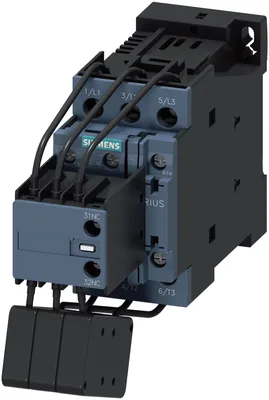
product brand nameSIRIUS
product designationcapacitor contactors
product type designation3RT26
General technical data
size of contactorS0
product extension auxiliary switchYok
at AC in hot operating state per pole0,9 W
without load current share typical1,7 W
type of calculation of power loss current-dependentquadratic
of main circuit with degree of pollution 3 rated value690 V
of auxiliary circuit with degree of pollution 3 rated value690 V
of main circuit rated value6 kV
of auxiliary circuit rated value6 kV
maximum permissible voltage for protective separation between coil and main contacts according to EN 60947-1400 V
at AC8,3 g / 5 ms, 5,3 g / 10 ms
at DC10g / 5 ms, 7,5g / 10 ms
at AC13,5 g / 5 ms, 8,3 g / 10 ms
at DC15 g / 5 ms, 10 g / 10 ms
of the contactor with added auxiliary switch block typical3.000.000
electrical endurance (operating cycles)200.000
reference code according to IEC 81346-2Q
Substance Prohibitance (day/month/year)05/01/2014
SVHC substance nameLead CAS-Yok. 7439-92-1 Lead monoxide (lead oxide) CAS-Yok. 1317-36-8 2-methyl-1-(4-methylthiophenyl)-2-morpholinopropan-1-one CAS-Yok. 71868-10-5 Melamine CAS-Yok. 108-78-1
Net Weight0,717 kg
Ambient conditions
installation altitude at height above sea level maximum2.000 m
during operation-25... +60 °C
during storage-55... +80 °C
relative humidity minimum10 %
relative humidity at 55 °C according to IEC 60068-2-30 maximum95 %
Main circuit
number of poles for main current circuit3
number of NO contacts for main contacts3
number of NC contacts for main contacts0
operational current at AC-6b at 690 V at ambient temperature 60 °C rated value29 A
at 230 V at 50/60 Hz at ambient temperature 60 °C rated value4... 11,5 kvar
at 400 V at 50/60 Hz at ambient temperature 60 °C rated value7... 20 kvar
at 500 V at 50/60 Hz at ambient temperature 60 °C rated value8... 25 kvar
at 690 V at 50/60 Hz at ambient temperature 60 °C rated value11... 34 kvar
at AC500 1/h
at DC500 1/h
at 230 V maximum100 1/h
at 240 V maximum100 1/h
at 400 V maximum100 1/h
at 480 V maximum100 1/h
at 500 V maximum100 1/h
at 600 V maximum100 1/h
at 690 V maximum100 1/h
Control circuit/ Control
type of voltageAC/DC
type of voltage of the control supply voltageAC/DC
at 50 Hz rated value21... 28 V
at 60 Hz rated value21... 28 V
1 rated value50 Hz
2 rated value60 Hz
control supply voltage at DC rated value21... 28 V
initial value0,7
full-scale value1,3
at 50 Hz0,7... 1,3
at 60 Hz0,7... 1,3
inrush current peak3 A
duration of inrush current peak30 µs
pickup current mean value0,3 A
pickup current peak0,52 A
duration of pickup current180 ms
holding current mean value45 mA
apparent pick-up power of magnet coil at AC6,7 V·A
inductive power factor with closing power of the coil0,98
apparent holding power of magnet coil at AC2 V·A
inductive power factor with the holding power of the coil0,86
closing power of magnet coil at DC5,9 W
holding power of magnet coil at DC1,4 W
at AC50... 80 ms
at DC50... 80 ms
at AC30... 50 ms
at DC30... 50 ms
arcing time10 ms
control version of the switch operating mechanismStandard A1 - A2
at AC at 230 V maximum permissible7 mA
at DC at 24 V maximum permissible16 mA
Auxiliary circuit
number of NC contacts for auxiliary contacts2
attachable0
instantaneous contact2
number of NO contacts for auxiliary contacts1
attachable0
instantaneous contact1
operational current of auxiliary contacts at AC-12 maximum10 A
at 230 V6 A
at 400 V3 A
at 690 V1 A
at 24 V6 A
at 60 V2 A
at 110 V1 A
at 125 V0,9 A
at 220 V0,3 A
contact reliability of auxiliary contacts0,00000001
UL/CSA ratings
contact rating of auxiliary contacts according to ULA600 / Q600
UL File Number (CCN)E31519 (NLDX, NLDX7)
Short-circuit protection
design of the miniature circuit breaker for short-circuit protection of the auxiliary circuit up to 230 VC characteristic: 10 A; 0,4 kA
for short-circuit protection of the main circuit with type of coordination 1 requiredgG: 63 A (690 V, 50 kA)
for short-circuit protection of the auxiliary switch requiredgG: 10 A (690 V, 1 kA)
Installation/ mounting/ dimensions
mounting position+/-180° rotation possible on dikey mounting surface; can be tilted forward ve backward by +/- 22,5° on dikey mounting surface
fastening methodscrew ve snap-on mounting onto 35 mm DIN rail according to DIN EN 50022
height135 mm
width45 mm
depth165 mm
with side-by-side mounting at the side10 mm
for grounded parts at the side10 mm
Connections/ Terminals
for main current circuitscrew-type terminals
for auxiliary and control circuitscrew-type terminals
at contactor for auxiliary contactsScrew-type terminals
of magnet coilscrew terminal
solid2x (1... 2,5 mm²), 2x (2,5... 10 mm²)
stranded2x (1... 2,5 mm²), 2x (2,5... 10 mm²)
solid or stranded2x (1... 2,5 mm²), 2x (2,5... 10 mm²)
finely stranded with core end processing2x (1... 2,5 mm²), 2x (2,5... 6 mm²), 1x 10 mm²
— solid2x (0,5... 1,5 mm²), 2x (0,75... 2,5 mm²), 2x 4 mm²
— solid or stranded2x (0,5... 1,5 mm²), 2x (0,75... 2,5 mm²), 2x 4 mm²
— finely stranded with core end processing2x (0,5... 1,5 mm²), 2x (0,75... 2,5 mm²)
for AWG cables for auxiliary contacts2x (20... 16), 2x (18... 14), 2x 12
at 40 °C1x 10 mm²
at 60 °C2x 10 mm²
AWG number as coded connectable conductor cross section for main contacts16... 8
Safety related data
mirror contact according to IEC 60947-4-1Yok
positively driven operation according to IEC 60947-5-1Yok
Electrical Safety
protection class IP on the front according to IEC 60529IP20
touch protection on the front according to IEC 60529finger-safe, for dikey contact from the front
Approvals Certificates
global warming potential [CO2 eq] / during manufacturing2,47 kg
global warming potential [CO2 eq] / during operation104 kg
global warming potential [CO2 eq] / after end of life-0.226 kg
global warming potential [CO2 eq] / total106 kg