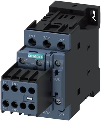
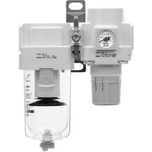
product brand nameSIRIUS
product designationPower contactor
product type designation3RT2
General technical data
size of contactorS0
function module for communicationYok
auxiliary switchYok
at AC in hot operating state9,6 W
at AC in hot operating state per pole3,2 W
without load current share typical5,9 W
type of calculation of power loss current-dependentquadratic
of main circuit with degree of pollution 3 rated value690 V
of auxiliary circuit with degree of pollution 3 rated value690 V
of main circuit rated value6 kV
of auxiliary circuit rated value6 kV
maximum permissible voltage for protective separation between coil and main contacts according to EN 60947-1400 V
at DC10g / 5 ms, 7,5g / 10 ms
at DC15 g / 5 ms, 10 g / 10 ms
of contactor typical10.000.000
of the contactor with added electronically optimized auxiliary switch block typical5.000.000
of the contactor with added auxiliary switch block typical10.000.000
reference code according to IEC 81346-2Q
Substance Prohibitance (day/month/year)10/01/2009
Net Weight0,65 kg
Ambient conditions
installation altitude at height above sea level maximum2.000 m
during operation-25... +60 °C
during storage-55... +80 °C
relative humidity minimum10 %
relative humidity at 55 °C according to IEC 60068-2-30 maximum95 %
Main circuit
number of poles for main current circuit3
number of NO contacts for main contacts3
number of NC contacts for main contacts0
at AC-3 rated value maximum690 V
at AC-3e rated value maximum690 V
at AC-1 at 400 V at ambient temperature 40 °C rated value50 A
— up to 690 V at ambient temperature 40 °C rated value50 A
— up to 690 V at ambient temperature 60 °C rated value42 A
— at 400 V rated value38 A
— at 500 V rated value32 A
— at 690 V rated value21 A
— at 400 V rated value38 A
— at 500 V rated value32 A
— at 690 V rated value21 A
at AC-4 at 400 V rated value22 A
at AC-5a up to 690 V rated value44 A
at AC-5b up to 400 V rated value31,5 A
— up to 230 V for current peak value n=20 rated value30,8 A
— up to 400 V for current peak value n=20 rated value30,8 A
— up to 500 V for current peak value n=20 rated value30,8 A
— up to 690 V for current peak value n=20 rated value21 A
— up to 230 V for current peak value n=30 rated value20,5 A
— up to 400 V for current peak value n=30 rated value20,5 A
— up to 500 V for current peak value n=30 rated value21,4 A
— up to 690 V for current peak value n=30 rated value21 A
minimum cross-section in main circuit at maximum AC-1 rated value10 mm²
at 400 V rated value12 A
at 690 V rated value12 A
— at 24 V rated value35 A
— at 60 V rated value20 A
— at 110 V rated value4,5 A
— at 220 V rated value1 A
— at 440 V rated value0,4 A
— at 600 V rated value0,25 A
— at 24 V rated value35 A
— at 60 V rated value35 A
— at 110 V rated value35 A
— at 220 V rated value5 A
— at 440 V rated value1 A
— at 600 V rated value0,8 A
— at 24 V rated value35 A
— at 60 V rated value35 A
— at 110 V rated value35 A
— at 220 V rated value35 A
— at 440 V rated value2,9 A
— at 600 V rated value1,4 A
— at 24 V rated value20 A
— at 60 V rated value5 A
— at 110 V rated value2,5 A
— at 220 V rated value1 A
— at 440 V rated value0,09 A
— at 600 V rated value0,06 A
— at 24 V rated value35 A
— at 60 V rated value35 A
— at 110 V rated value15 A
— at 220 V rated value3 A
— at 440 V rated value0,27 A
— at 600 V rated value0,16 A
— at 24 V rated value35 A
— at 60 V rated value35 A
— at 110 V rated value35 A
— at 220 V rated value10 A
— at 440 V rated value0,6 A
— at 600 V rated value0,6 A
— at 230 V rated value11 kW
— at 400 V rated value18,5 kW
— at 500 V rated value18,5 kW
— at 690 V rated value18,5 kW
— at 230 V rated value11 kW
— at 400 V rated value18,5 kW
— at 500 V rated value18,5 kW
— at 690 V rated value18,5 kW
at 400 V rated value6 kW
at 690 V rated value10,3 kW
up to 230 V for current peak value n=20 rated value12,2 kVA
up to 400 V for current peak value n=20 rated value21,3 kVA
up to 500 V for current peak value n=20 rated value26,6 kVA
up to 690 V for current peak value n=20 rated value25 kVA
up to 230 V for current peak value n=30 rated value8,1 kVA
up to 400 V for current peak value n=30 rated value14,2 kVA
up to 500 V for current peak value n=30 rated value18,5 kVA
up to 690 V for current peak value n=30 rated value25 kVA
limited to 1 s switching at zero current maximum593 A; Use minimum cross-section acc. to AC-1 rated value
limited to 5 s switching at zero current maximum341 A; Use minimum cross-section acc. to AC-1 rated value
limited to 10 s switching at zero current maximum260 A; Use minimum cross-section acc. to AC-1 rated value
limited to 30 s switching at zero current maximum199 A; Use minimum cross-section acc. to AC-1 rated value
limited to 60 s switching at zero current maximum162 A; Use minimum cross-section acc. to AC-1 rated value
at DC1.500 1/h
at AC-1 maximum1.000 1/h
at AC-2 maximum750 1/h
at AC-3 maximum750 1/h
— maximum750 1/h
at AC-4 maximum250 1/h
Control circuit/ Control
type of voltage of the control supply voltageDC
control supply voltage at DC rated value24 V
initial value0,8
full-scale value1,1
closing power of magnet coil at DC5,9 W
holding power of magnet coil at DC5,9 W
at DC50... 170 ms
at DC15... 18 ms
arcing time10 ms
control version of the switch operating mechanismStandard A1 - A2
Auxiliary circuit
number of NC contacts for auxiliary contacts instantaneous contact2
number of NO contacts for auxiliary contacts instantaneous contact2
operational current at AC-12 maximum10 A
at 230 V rated value6 A
at 400 V rated value3 A
at 500 V rated value2 A
at 690 V rated value1 A
at 24 V rated value10 A
at 48 V rated value6 A
at 60 V rated value6 A
at 110 V rated value3 A
at 125 V rated value2 A
at 220 V rated value1 A
at 600 V rated value0,15 A
at 24 V rated value6 A
at 48 V rated value2 A
at 60 V rated value2 A
at 110 V rated value1 A
at 125 V rated value0,9 A
at 220 V rated value0,3 A
at 600 V rated value0,1 A
contact reliability of auxiliary contacts1 faulty switching per 100 million (17 V, 1 mA)
UL/CSA ratings
at 480 V rated value34 A
at 600 V rated value27 A
— at 110/120 V rated value3 hp
— at 230 V rated value5 hp
— at 200/208 V rated value10 hp
— at 220/230 V rated value10 hp
— at 460/480 V rated value25 hp
— at 575/600 V rated value25 hp
contact rating of auxiliary contacts according to ULA600 / Q600
UL File Number (CCN)E31519 (NLDX, NLDX7)
Short-circuit protection
design of the miniature circuit breaker for short-circuit protection of the auxiliary circuit up to 230 VC characteristic: 10 A; 0,4 kA
— with type of coordination 1 requiredgG: 125 A (690 V,100 kA), aM: 50 A (690 V,100 kA), BS88: 125 A (415 V,80 kA)
— with type of coordination 2 requiredgG: 50 A (690 V, 100 kA), aM: 25 A (690 V, 100 kA), BS88: 50 A (415 V, 80 kA)
for short-circuit protection of the auxiliary switch requiredgG: 10 A (500 V, 1 kA)
Installation/ mounting/ dimensions
mounting position+/-180° rotation possible on dikey mounting surface; can be tilted forward ve backward by +/- 22,5° on dikey mounting surface
fastening method side-by-side mountingVar
fastening methodscrew ve snap-on mounting onto 35 mm DIN rail according to DIN EN 60715
height85 mm
width45 mm
depth151 mm
— forwards10 mm
— upwards10 mm
— downwards10 mm
— at the side0 mm
— forwards10 mm
— upwards10 mm
— at the side6 mm
— downwards10 mm
— forwards10 mm
— upwards10 mm
— downwards10 mm
— at the side6 mm
Connections/ Terminals
for main current circuitscrew-type terminals
for auxiliary and control circuitscrew-type terminals
at contactor for auxiliary contactsScrew-type terminals
of magnet coilscrew terminal
— solid2x (1... 2,5 mm²), 2x (2,5... 10 mm²)
— solid or stranded2x (1... 2,5 mm²), 2x (2,5... 10 mm²)
— finely stranded with core end processing2x (1... 2,5 mm²), 2x (2,5... 6 mm²), 1x 10 mm²
for AWG cables for main contacts2x (16... 12), 2x (14... 8)
solid1... 10 mm²
stranded1... 10 mm²
finely stranded with core end processing1... 10 mm²
solid or stranded0,5... 2,5 mm²
finely stranded with core end processing0,5... 2,5 mm²
— solid or stranded2x (0,5... 1,5 mm²), 2x (0,75... 2,5 mm²)
— finely stranded with core end processing2x (0,5... 1,5 mm²), 2x (0,75... 2,5 mm²)
for AWG cables for auxiliary contacts2x (20... 16), 2x (18... 14)
AWG number as coded connectable conductor cross section for main contacts16... 8
AWG number as coded connectable conductor cross section for auxiliary contacts20... 14
Safety related data
mirror contact according to IEC 60947-4-1Var
positively driven operation according to IEC 60947-5-1Yok
suitable for safety functionVar
suitability for use safety-related switching OFFVar
service life maximum20 a
test wear-related service life necessaryVar
with low demand rate according to SN 3192040 %
with high demand rate according to SN 3192073 %
B10 value with high demand rate according to SN 319201.000.000
failure rate [FIT] with low demand rate according to SN 31920100 FIT
ISO 13849
device type according to ISO 13849-13
overdimensioning according to ISO 13849-2 necessaryVar
IEC 61508
safety device type according to IEC 61508-2Type A
Electrical Safety
protection class IP on the front according to IEC 60529IP20
touch protection on the front according to IEC 60529finger-safe, for dikey contact from the front
Approvals Certificates
global warming potential [CO2 eq] / during manufacturing2,65 kg
global warming potential [CO2 eq] / during operation219 kg
global warming potential [CO2 eq] / after end of life-0.639 kg
global warming potential [CO2 eq] / total221 kg