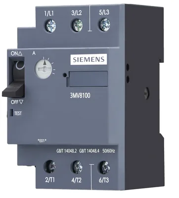
Detayları Gör
Siemens
3MV8100-0MB00
MFR #3MV8100-0MB00
SKU #YLSTQVYRHTPPWXE
Web sitemizde size daha iyi bir deneyim sunmak için çerezler kullanıyoruz. Çerezler, site performansını artırmak, içerikleri kişiselleştirmek ve trafiği analiz etmek için kullanılır.
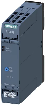
Fotoğraf, ürünün gerçek halini yansıtmayabilir. Tüm detaylar için ürünün adına ve özelliklerine bakınız.
thermistor motor koruması röle standart evaluation ünite 22,5 mm muhafaza yaylı klemens 2 komütatör kontak Us = 24 V AC/DC manuel/auto/uzak RESET ile ATEX approval 2 LEDs (ready/tripped) safe electrical isolation test/RESET buton wire-break monitoring short-circuit monitoring non-volatile
thermistor motor koruması röle standart evaluation ünite 22,5 mm muhafaza yaylı klemens 2 komütatör kontak Us = 24 V AC/DC manuel/auto/uzak RESET ile ATEX approval 2 LEDs (ready/tripped) safe electrical isolation test/RESET buton wire-break monitoring short-circuit monitoring non-volatile
Siemens 3RN2013-2BA30 motorla birlikte kullanılabilen, ayrı olarak tedarik edilen orijinal aksesuarlar aşağıda listelenmiştir. Koda tıklayarak aksesuarın sayfasına ve uyumlu diğer motorlara ulaşabilirsiniz.
| Parça no | Açıklama | Uyumlu motor |
|---|---|---|
| 3ZY1311-0AA00 | Aksesuar · Further accessories | |
| 3ZY1122-1BA00 | Aksesuar · Removable terminals | |
| 3ZY1440-1AA00 | Aksesuar · Further accessories | |
| 3ZY1122-2BA00 | Aksesuar · Removable terminals |
Siemens
MFR #3MV8100-0MB00
SKU #YLSTQVYRHTPPWXE
Siemens
MFR #3MV8100-0MC00
SKU #YLSNDRLO7GD0JC3
Siemens
MFR #3MV8100-0MD00
SKU #YLSLDR7SAMNEI7
Siemens
MFR #3MV8100-0ME00
SKU #YLSQYIXF5Z6DOGW
Siemens
MFR #3MV8100-0MF00
SKU #YLSE4VVERJVVVFH
Siemens
MFR #3MV8100-0MG00
SKU #YLSI4OKULAP3QK
Siemens
MFR #3MV8100-0MH00
SKU #YLSCUEFEDHRZRUJ
Siemens
MFR #3MV8100-0MJ00
SKU #YLSMBKZVBRAS5T
Siemens
MFR #3MV8100-0MK00
SKU #YLS3JCVHPICJ2VL
Siemens
MFR #3MV8100-0ML00
SKU #YLSMFZC3SXLCXHP
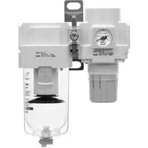
SMC
MFR #AC40B-N04G-RZ-B F/R COMBO MODULAR
SKU #YLS1HII4JHHH09L
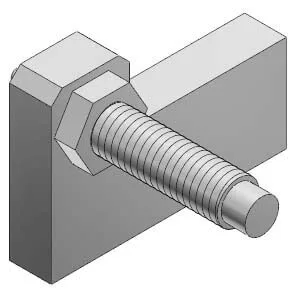
SMC
MFR #MXS-AS16L
SKU #YLSAP0XXFGFSWY6
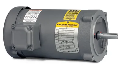
Baldor
MFR #VM8001-5
SKU #YLS3TOWVXWW0DHP
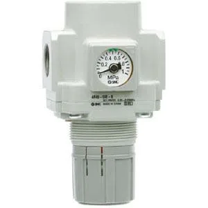
SMC
MFR #AR30-N02E-1Z-B
SKU #YLSYFNHADE6GRKV
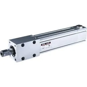
SMC
MFR #MTS32-150M
SKU #YLSSJCSBTRLX2P7
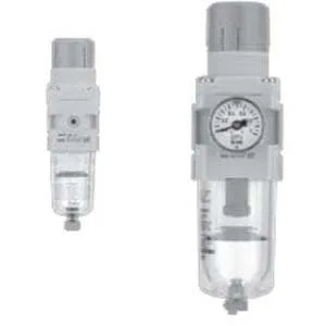
SMC
MFR #AW20-N02CG-6CZ-B
SKU #YLSNOOF0IBCZ3J3
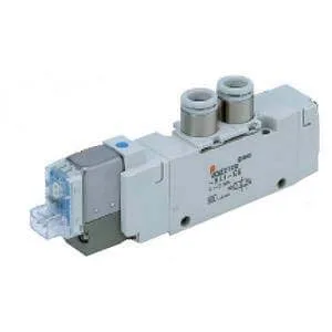
SMC
MFR #VQZ2121-5LO1-N3T
SKU #YLSEL35MGGQ9FOL
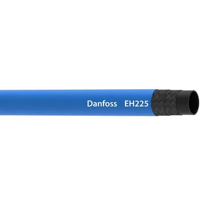
Danfoss Aeroquip LLC
MFR #EH22512
SKU #YLSRZ91UGVO64DG
SMC
MFR #MXQ25L-40B-M9NZ
SKU #YLSD1VANMRI726Z
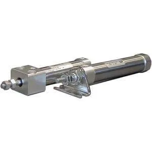
SMC
MFR #CM2B40-75Z
SKU #YLSOGLJ512KWTEJ
Siemens 3RN2013-2BA30 fiyatSiemens 3RN2013-2BA30 teklif alSiemens 3RN2013-2BA30 satın al3RN2013-2BA30 fiyat3RN2013-2BA30 stok durumuSiemens yedek parçaSiemens 3RN2013-2BA30 muadilSiemens 3RN2013-2BA30 teknik özellikler