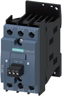
product brand nameSIRIUS
product designationsolid-state reversing contactor
design of the product2-pole controlled
product type designation3RF34
_1 of the accessories that can be ordered3RA2921-1BA00
_2 of the accessories that can be ordered3RF3900-0QA88
_1 of the accessories that can be orderedLink module
_2 of the accessories that can be orderedConnection adapter
General technical data
certificate of suitabilityCE / UL / CSA / CCC / C-Tick (RCM)
product functioninstantaneous switching
at AC in hot operating state7 W
at AC in hot operating state per pole2,33 W
without load current share typical0,4 W
type of calculation of power loss current-dependentlinear
insulation voltage rated value600 V
degree of pollution3
surge voltage resistance of main circuit rated value6 kV
protection class IPIP20
protection class IP on the front according to IEC 60529IP20
shock resistance according to IEC 60068-2-2715 g / 11 ms
vibration resistance according to IEC 60068-2-62 g
reference code according to IEC 81346-2Q
Substance Prohibitance (day/month/year)05/28/2009
SVHC substance nameLead CAS-Yok. 7439-92-1 Lead monoxide (lead oxide) CAS-Yok. 1317-36-8 2-methyl-1-(4-methylthiophenyl)-2-morpholinopropan-1-one CAS-Yok. 71868-10-5 Melamine CAS-Yok. 108-78-1
Net Weight0,287 kg
Main circuit
number of poles for main current circuit3
number of NO contacts for main contacts2
number of NC contacts for main contacts0
type of voltage of the operating voltageAC
— at 50 Hz rated value48... 480 V
— at 60 Hz rated value48... 480 V
operating frequency rated value50... 60 Hz
relative symmetrical tolerance of the operating frequency10 %
at 50 Hz40... 506 V
at 60 Hz40... 506 V
at AC-3 at 400 V rated value3,8 A
at AC-53a at 400 V at ambient temperature 40 °C rated value3,8 A
operational current minimum500 mA
at AC-3 at 400 V rated value1,5 kW
rate of voltage rise at the thyristor for main contacts maximum permissible1.000 V/µs
blocking voltage at the thyristor for main contacts maximum permissible1.200 V
reverse current of the thyristor10 mA
derating temperature40 °C
surge current resistance rated value600 A
I2t value maximum1.800 A²·s
Control circuit/ Control
type of voltage of the control supply voltageDC
control supply voltage at DC rated value24 V
initial value for signal <1> detection15 V
full-scale value for signal<0> recognition5 V
symmetrical line frequency tolerance5 Hz
initial value0,63
full-scale value1,25
at DC2 mA
control current at DC rated value15 mA
ON-delay time5 ms
OFF-delay time5 ms; additionally maks. one half-wave
switchover delay of reversing contactor60... 100 ms
Installation/ mounting/ dimensions
mounting positiondikey
fastening method side-by-side mountingVar
fastening methodscrew ve snap-on mounting onto 35 mm DIN rail
design of the thread of the screw for securing the equipmentM4
height95 mm
width45 mm
depth113,8 mm
upwards70 mm
downwards50 mm
Connections/ Terminals
product component removable terminal for auxiliary and control circuitVar
for main current circuitscrew-type terminals
for auxiliary and control circuitscrew-type terminals
— solid2x (1,5... 2,5 mm²), 2x (2,5... 6 mm²)
— finely stranded with core end processing2x (1... 2,5 mm²), 2x (2,5... 6 mm²), 1x 10 mm²
for AWG cables for main contacts2x (14... 10)
solid or stranded1,5... 6 mm²
finely stranded with core end processing1... 10 mm²
— solid1x (0,5... 2,5 mm²), 2x (0,5... 1 mm²)
— finely stranded with core end processing1x (0,5... 2,5 mm²), 2x (0,5... 1 mm²)
— finely stranded without core end processing1x (0,5... 2,5 mm²), 2x (0,5... 1 mm²)
for AWG cables for auxiliary and control contacts1x (20... 12)
AWG number as coded connectable conductor cross section for main contacts14... 10
for main contacts with screw-type terminals2... 2,5 N·m
for auxiliary and control contacts with screw-type terminals0,5... 0,6 N·m
for main contacts with screw-type terminals18... 22 lbf·in
for auxiliary and control contacts with screw-type terminals7,5... 5,3 lbf·in
for main contactsM4
of the auxiliary and control contactsM3
for main contacts10 mm
for auxiliary and control contacts7 mm
UL/CSA ratings
at 480 V rated value3,4 A
at 200/208 V rated value0,5 hp
at 220/230 V rated value0,75 hp
at 460/480 V rated value2 hp
Safety related data
proportion of dangerous failures with high demand rate according to SN 3192050 %
MTTF with high demand rate39 a
IEC 61508
T1 value for proof test interval or service life according to IEC 615086 a
Electrical Safety
touch protection on the front according to IEC 60529finger-safe, for dikey contact from the front
Ambient conditions
installation altitude at height above sea level maximum1.000 m
during operation-25... +60 °C
during storage-55... +80 °C
Electromagnetic compatibility
due to burst according to IEC 61000-4-42 kV / 5 kHz, behavior criterion 2
due to conductor-earth surge according to IEC 61000-4-52 kV, behavior criterion 2
due to conductor-conductor surge according to IEC 61000-4-51 kV, behavior criterion 2
due to high-frequency radiation according to IEC 61000-4-6140 dBuV in the frequency range 0,15... 80 MHz, behavior criterion 1
electrostatic discharge according to IEC 61000-4-24 kV contact discharging / 8 kV air discharging, behavior criterion 2
conducted HF interference emissions according to CISPR11Class A for industrial environment
field-bound HF interference emission according to CISPR11Class A for industrial environment
Short-circuit protection, design of the fuse link
of full range R fuse link for semiconductor protection at NH design usable3NE1813-0
of full range R fuse link for semiconductor protection at cylindrical design usable5SE1335
of back-up R fuse link for semiconductor protection at NH design usable3NE8015-1
of back-up R fuse link for semiconductor protection at cylindrical design 10 x 38 mm usable3NC1020
of back-up R fuse link for semiconductor protection at cylindrical design 14 x 51 mm usable3NC1415
of back-up R fuse link for semiconductor protection at cylindrical design 22 x 58 mm usable3NC2220
at NH design usable3NA3801-6
at cylindrical design 10 x 38 mm usable3NW6001-1
at cylindrical design 14 x 51 mm usable3NW6101-1