General information
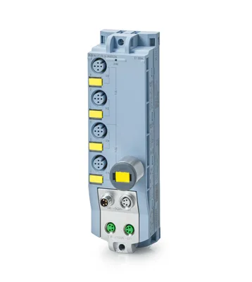
Product type designationF-DI 4+F-DQ 2x24VDC/2A, 4xM12
Product function
I&M dataYes; I&M0 to I&M3
Engineering with
STEP 7 TIA Portal configurable/integrated from versionSTEP 7 V17 or higher
Operating mode
DIYes
DQYes
Supply voltage
Rated value (DC)24 V
power supply according to NEC Class 2 requiredNo
Load voltage 1L+
Rated value (DC)24 V
permissible range, lower limit (DC)20.4 V
permissible range, upper limit (DC)28.8 V
Reverse polarity protectionYes; against destruction
Load voltage 2L+
Rated value (DC)24 V
permissible range, lower limit (DC)20.4 V
permissible range, upper limit (DC)28.8 V
Reverse polarity protectionYes; against destruction; outputs applied with reversed polarity for loads connected between M-switch and 2L+ will conduct
Input current
Current consumption (rated value)55 mA (1L+) / 40 mA (2L+); without load
from load voltage 1L+ (unswitched voltage)4 A; Maximum value
from load voltage 2L+, max.4 A; Maximum value
Encoder supply
Number of outputs2
24 V encoder supply
Short-circuit protectionYes; per load voltage, electronic (response threshold 0.7 A to 1.7 A)
Output current, max.1 A; total current of all encoders, max. 0.5 A per load voltage; maximum of 2.0 V drop
Power loss
Power loss, typ.4.7 W
Address space per module
Inputs8 byte
Outputs6 byte
Digital inputs
Number of digital inputs4
Input characteristic according to IEC 61131Type 1
all mounting positions
— up to 55 °C, max.4
Input voltage
Rated value (DC)24 V
for signal "0"-30 to +5 V
for signal "1"+15 to +30 V
Input current
for signal "1", typ.4.85 mA
for standard inputs
— parameterizableYes
— at "0" to "1", min.0.8 ms
— at "0" to "1", max.12.8 ms
— at "1" to "0", min.0.8 ms
— at "1" to "0", max.12.8 ms
Cable length
unshielded, max.30 m
Digital outputs
Number of digital outputs2
in groups of2
Short-circuit protectionYes; per channel, electronic
Response threshold, typ.10 A; measured at M-switch, threshold for P-switch is higher
Open-circuit detectionYes; per channel, only detects when output is off
Overload protectionYes
Response threshold, typ.3.4 A; measured at P-switch
Limitation of inductive shutdown voltage toP-switch: -26 V DC referenced to 2M, M-switch: +48 V DC referenced to 2M
Switching capacity of the outputs
on lamp load, max.10 W
Load resistance range
lower limit12 Ω
upper limit2 kΩ
Output voltage
for signal "1", min.L+ (-2.0 V), P-switch is L+ (-1.5 V), M-switch is 0.5 V
Output current
for signal "1" rated value2 A
for signal "0" residual current, max.0.5 mA
Switching frequency
with resistive load, max.30 Hz
with inductive load, max.0.1 Hz
on lamp load, max.10 Hz
Total current of the outputs
Current per group, max.4 A
Cable length
unshielded, max.30 m
Connectable encoders
2-wire sensorNo
— permissible quiescent current (2-wire sensor), max.0.5 mA
Interrupts/diagnostics/status information
Substitute values connectableNo
Alarms
Diagnostic alarmYes; Parameterizable
Diagnoses
Monitoring the supply voltageYes
Wire breakYes; outputs when off
short-circuitYes; inputs, outputs, encoder supply
Diagnostics indication LED
Channel status displayYes; green LED
for channel diagnosticsYes; red LED
for module diagnosticsYes; green/red LED
For load voltage monitoringYes; green LED
Potential separation
between the load voltagesYes
Potential separation channels
between the channels, in groups of4 DI channels are isolated from 2 DQ channels
between the channels and backplane busYes
between the channels and the power supply of the electronicsDI channels are non-isolated from supply voltage 1L+ and DQ channels are isolated from the supply voltage 1L+
Isolation
Isolation tested with707 V DC (type test)
Degree and class of protection
IP degree of protectionIP65/67
Highest safety class achievable in safety mode
Performance level according to ISO 13849-1PLd (DI single-channel), PLe (DI two-channel, DQ)
Category according to ISO 13849-1Cat. 3 (DI single-channel), Cat. 4 (DI two-channel, DQ)
SIL acc. to IEC 61508SIL 2 (DI single-channel), SIL 3 (DI two-channel, DQ)
Probability of failure (for service life of 20 years and repair time of 100 hours)
— Low demand mode: PFDavg in accordance with SIL2< 1.00E-03 DI single-channel; < 1.00E-03 DQ with dark test disabled
— Low demand mode: PFDavg in accordance with SIL3< 1.00E-05 DI two-channel; < 2.00E-05 DQ with dark test enabled
— High demand/continuous mode: PFH in accordance with SIL2< 1.00E-08 1/h DI single-channel; < 1.00E-07 1/h DQ with dark test disabled
— High demand/continuous mode: PFH in accordance with SIL3< 1.00E-09 1/h DI two-channel; < 1.00E-08 1/h DQ with dark test enabled
Ambient temperature during operation
min.-30 °C
max.55 °C
Connection method
Design of electrical connection for the inputs and outputsM12, 5-pole
Design of electrical connection for supply voltageM8, 4-pin
ET-Connection
ET-ConnectionM8, 4-pin, shielded
Dimensions
Width45 mm
Height159 mm
Depth40 mm
Weights
Weight, approx.220 g