General information
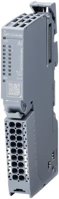
Product type designationAI 4xRTD 2-/3-/4-wire
HW functional statusfrom FS01
Firmware versionV1.0.0
FW update possibleYes
Color code for module-specific color-coded labelCC00
Product function
I&M dataYes; I&M0 to I&M3
Isochronous modeNo
Measuring range scalableNo
Engineering with
STEP 7 TIA Portal configurable/integrated from versionSTEP 7 V18 or higher; MicroWin V3.0 or higher; Configuration in ES via GSDML;
PROFINET from GSD version/GSD revisionGSDML V2.45
Operating mode
OversamplingNo
MSINo
Supply voltage
Rated value (DC)24 V
permissible range, lower limit (DC)20.4 V
permissible range, upper limit (DC)28.8 V
Reverse polarity protectionYes
external protection for power supply linesYes; 24 V DC/10 A miniature circuit breaker with type B or C tripping characteristic
Input current
Current consumption (rated value)16 mA
Current consumption, max.20 mA
Current carrying capacity
For P1 and P2 bus, max.10 A
Power loss
Power loss, typ.0.32 W
Address space per module
Address space per module, max.8 byte
Inputs8 byte
Hardware configuration
Automatic encodingNo
Mechanical coding elementNo
Formation of potential groups
support of potential groupsYes
Analog inputs
Number of analog inputs4; Differential inputs
For resistance/resistance thermometer measurement4
Constant measurement current for resistance-type transmitter, typ.0.25 mA
Cycle time (all channels), min.Sum of the basic conversion times and additional processing times (depending on the parameterization of the active channels)
Technical unit for temperature measurement adjustableYes; Celsius / Fahrenheit
Input ranges (rated values), resistance thermometer
Cu 10Yes; 16 bit incl. sign
— Input resistance (Cu 10)1 MΩ
Cu 50Yes; 16 bit incl. sign
— Input resistance (Cu 50)1 MΩ
Cu 100Yes; 16 bit incl. sign
— Input resistance (Cu 100)1 MΩ
Ni 100Yes; 16 bit incl. sign
— Input resistance (Ni 100)1 MΩ
Ni 1000Yes; 16 bit incl. sign
— Input resistance (Ni 1000)1 MΩ
Ni 120Yes; 16 bit incl. sign
— Input resistance (Ni 120)1 MΩ
Pt 100Yes; 16 bit incl. sign
— Input resistance (Pt 100)1 MΩ
Pt 1000Yes; 16 bit incl. sign
— Input resistance (Pt 1000)1 MΩ
Pt 200Yes; 16 bit incl. sign
— Input resistance (Pt 200)1 MΩ
Pt 500Yes; 16 bit incl. sign
— Input resistance (Pt 500)1 MΩ
Input ranges (rated values), resistors
0 to 150 ohmsYes; 15 bit
— Input resistance (0 to 150 ohms)1 MΩ
0 to 300 ohmsYes; 15 bit
— Input resistance (0 to 300 ohms)1 MΩ
0 to 600 ohmsYes; 15 bit
— Input resistance (0 to 600 ohms)1 MΩ
Cable length
shielded, max.200 m
Analog value generation for the inputs
Measurement principleintegrating (Sigma-Delta)
Integration and conversion time/resolution per channel
Resolution with overrange (bit including sign), max.16 bit
Integration time, parameterizableYes
— additional processing time for wire-break check2 ms
— additional power line wire-break check1 ms
Interference voltage suppression for interference frequency f1 in Hz16.6 / 50 / 60 Hz
Conversion time (per channel)180 / 60 / 50 ms
Smoothing of measured values
Number of smoothing levels4; None; 4/8/16 times
parameterizableYes
Step: NoneYes
Step: lowYes; 4x smoothing
Step: MediumYes; 8x smoothing
Step: HighYes; 16x smoothing
Connection of signal encoders
for resistance measurement with two-wire connectionYes
for resistance measurement with three-wire connectionYes
for resistance measurement with four-wire connectionYes
Errors/accuracies
Linearity error (relative to input range), (+/-)0.1 %
Temperature error (relative to input range), (+/-)0.0009 %/K
Crosstalk between the inputs, min.-50 dB
Repeat accuracy in steady state at 25 °C (relative to input range), (+/-)0.05 %
Operational error limit in overall temperature range
Resistance, relative to input range, (+/-)0.1 %
Basic error limit (operational limit at 25 °C)
Resistance, relative to input range, (+/-)0.05 %
Interference voltage suppression for f = n x (f1 +/- 1 %), f1 = interference frequency
Series mode interference (peak value of interference < rated value of input range), min.70 dB
Interrupts/diagnostics/status information
Diagnostics functionYes
Alarms
Diagnostic alarmYes
Limit value alarmNo
Diagnoses
Monitoring the supply voltageYes
Wire breakYes; module-wise
Short-circuitNo
Group errorNo
Overflow/UnderflowYes; module-wise
Diagnostics indication LED
Monitoring of the supply voltage (PWR-LED)Yes; green LED
Channel status displayYes; green LED
for channel diagnosticsNo
for module diagnosticsYes; green/red DIAG LED
Potential separation
between backplane bus and supply voltageYes
Potential separation analog inputs
between the channelsNo
between the channels and backplane busYes
between the channels and the power supply of the electronicsYes
Isolation
Isolation tested with500 V AC/707 V DC, type test
Ecological footprint
environmental product declarationYes
Global warming potential
— global warming potential, (total) [CO2 eq]9.28 kg
— global warming potential, (during production) [CO2 eq]3.16 kg
— global warming potential, (during operation) [CO2 eq]6.21 kg
— global warming potential, (after end of life cycle) [CO2 eq]-0.106 kg
Use in hazardous areas
EAC ExNo
Ambient temperature during operation
horizontal installation, min.-30 °C
horizontal installation, max.60 °C
vertical installation, min.-30 °C
vertical installation, max.50 °C
Altitude during operation relating to sea level
Installation altitude above sea level, max.5 000 m; restrictions for installation altitudes > 2 000 m, see ET 200BL system manual
Terminals
Conductor cross-section, min.0.14 mm²; follow detailed information in System manual of ET 200BL
Conductor cross-section, max.2.5 mm²; follow detailed information in System manual of ET 200BL
Number of process terminals to I/O module16
Number of terminals with connection to P1 and P2 bus2
Dimensions
Width15 mm
Height117 mm
Depth74 mm
Weights
Weight, approx.81 g