General information
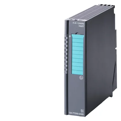
Product type designation4AI TC
HW functional status7
Firmware versionV1.0.1
CiR - Configuration in RUN
Reparameterization possible in RUNYes
Installation type/mounting
Rack mountingNo
Front mountingYes
Rail mountingYes
Wall mounting/direct mountingNo
Supply voltage
Type of supply voltageDC
permissible range, lower limit (DC)20.4 V
permissible range, upper limit (DC)28.8 V
Input current
Current consumption, typ.17 mA
from load voltage (power bus), max.30 mA
Power loss
Power loss, typ.0.4 W
Hardware configuration
Fieldbus connection via separate transceiverYes
Analog inputs
Number of analog inputs4
Cycle time (all channels) max.320 ms; 66 ms basic conversion time x 4 channels with interference frequency suppression 60 Hz, 80 ms basic conversion time x 4 channels with interference frequency suppression 50 Hz
Technical unit for temperature measurement adjustableYes
Input ranges
VoltageYes
CurrentNo
ThermocoupleYes
Resistance thermometerNo
ResistanceNo
Input ranges (rated values), voltages
-80 mV to +80 mVYes
— Input resistance (-80 mV to +80 mV)1 000 kΩ
Input ranges (rated values), thermocouples
type BYes
— Input resistance (Type B)1 000 kΩ
type CYes
— Input resistance (Type C)1 000 kΩ
Type EYes
— Input resistance (Type E)1 000 kΩ
Type JYes
— Input resistance (type J)1 000 kΩ
Type KYes
— Input resistance (Type K)1 000 kΩ
Type LYes
— Input resistance (Type L)1 000 kΩ
Type NYes
— Input resistance (Type N)1 000 kΩ
Type RYes
— Input resistance (Type R)1 000 kΩ
Type SYes
— Input resistance (Type S)1 000 kΩ
Type TYes
— Input resistance (Type T)1 000 kΩ
Type UYes
— Input resistance (Type U)1 000 kΩ
Temperature compensation
— internal temperature compensationYes; via supplied TC sensor module
— external temperature compensation with compensations socketYes; via temperature value, acquired by an analog module of the same ET 200iSP station
Characteristic linearization
ParameterizableYes
— for thermocouplesYes
Cable length
shielded, max.50 m
Analog value generation for the inputs
Measurement principleintegrating (Sigma-Delta)
Integration and conversion time/resolution per channel
Resolution with overrange (bit including sign), max.16 bit
Integration time, parameterizableYes
Basic conversion time, including integration time (ms)80 ms at 50 Hz; 66 ms at 60 Hz
— additional conversion time for wire-break monitoring5 ms
Interference voltage suppression for interference frequency f1 in Hz50 / 60 Hz
Smoothing of measured values
ParameterizableYes; in 4 stages
Step: NoneYes; 1x cycle time
Step: lowYes; 4x cycle time
Step: MediumYes; 32x cycle time
Step: HighYes; 64x cycle time
Errors/accuracies
Linearity error (relative to input range), (+/-)0.015 %
Temperature error (relative to input range), (+/-)0.02 %/K
Crosstalk between the inputs, min.-50 dB
Repeat accuracy in steady state at 25 °C (relative to input range), (+/-)0.01 %
Operational error limit in overall temperature range
Voltage, relative to input range, (+/-)0.15 %
Basic error limit (operational limit at 25 °C)
Voltage, relative to input range, (+/-)0.1 %
Interference voltage suppression for f = n x (f1 +/- 1 %), f1 = interference frequency
Series mode interference (peak value of interference < rated value of input range), min.70 dB
Common mode interference, min.90 dB
Interfaces
Number of PROFINET interfaces0
Protocols
Supports protocol for PROFINET IONo
PROFIsafeNo
PROFIBUSNo
Further protocols
other bus systemsNo
Alarms
Diagnostic alarmYes; Parameterizable
Limit value alarmYes; Parameterizable
Diagnoses
Diagnostic information readableYes
Wire breakYes; R > 1.7 kOhm
Diagnostics indication LED
Group error SF (red)Yes
Ex(i) characteristics
Module for Ex(i) protectionYes; for more Co/Lo combinations, see certificate IECEx KEM 05.0008
maximum values for connecting terminals for gas group IIC
Uo (no-load voltage), max.5.9 V
Io (short-circuit current), max.15 mA
Po (power output), max.23 mW
Co (permissible external capacity), max.43 µF
Lo (permissible external inductivity), max.100 mH
Potential separation
between channels and powerbusYes
Potential separation analog inputs
between the channelsYes; Functional
between the channels and backplane busYes
Degree and class of protection
IP degree of protectionIP30
Standards, approvals, certificates
CE markCE 0344
UKCA markDEKRA 21UKEX0086 Importer UK: Siemens plc Manchester M20 2UR
cULusLISTED E334384
FM approvalCLASSIFIED 3025852
Suitable for safety functionsNo
INMETRO certificateUL-BR 12.0071
reference designation according to IEC 81346-2 (2009)K
Highest safety class achievable in safety mode
acc. to EN 954n.a.
Performance level according to ISO 13849-1none
SIL acc. to IEC 61508No
Use in hazardous areas
ATEX markingII 2 G (1) G Ex ib [ia Ga] IIC T4 Gb II 2 G (1) D Ex ib [ia IIIC Da] IIC T4 Gb I M2 Ex ib [ia] I Mb
ATEX certificateKEMA 04 ATEX 1246
IECExIECEx KEM 05.0008
CCC Ex2020322316002943
EAC ExPB Ex ib [ia] I Mb 1Ex ib [ia Ga] IIC T4 Gb [Ex ia Da] IIIC
FM markingClass I, Zone 1 AEx ib [ia] IIC T4 Ex ib IIC T4 NI, Class I, DIV.2, GP. A,B,C,D T4 AIS, Class I, DIV.1, GP. A,B,C,D T4 DIP Class II, III, GP. E,F,G
Explosion protection category for gasATEX gas explosion protection, Zone 1
Explosion protection category for dustATEX dust explosion protection, Zone 21 always install in corresponding enclosure
associated equipment (Ex ia)Yes
associated equipment (Ex ib)Yes
Marine approval
Germanischer Lloyd (GL)Yes
American Bureau of Shipping (ABS)Yes
Bureau Veritas (BV)Yes
Det Norske Veritas (DNV)Yes
Connection method
Design of electrical connectionScrew/spring-type terminal
Dimensions
Width30 mm
Height129 mm
Depth136.5 mm
Weights
Weight, approx.230 g