General information
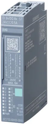
Product type designationDI 8x/DQ 8x24VDC/0,5A ST
HW functional statusFS01
Firmware versionV1.0
FW update possibleYes
usable BaseUnitsBU type A0
Color code for module-specific color-coded labelCC00
Product function
I&M dataYes; I&M0 to I&M3
Isochronous modeNo
Engineering with
STEP 7 TIA Portal configurable/integrated from versionSTEP 7 V18 or higher with HSP 0401
PROFIBUS from GSD version/GSD revisionOne GSD file each, Revision 3 and 5 and higher
PROFINET from GSD version/GSD revisionGSDML V2.42
Operating mode
DIYes
DQYes
DQ with energy-saving functionNo
PWMNo
OversamplingNo
MSONo
Redundancy
Redundancy capabilityNo
Supply voltage
Rated value (DC)24 V
permissible range, lower limit (DC)19.2 V
permissible range, upper limit (DC)28.8 V
Reverse polarity protectionYes
Input current
Current consumption, max.35 mA; without load
Output voltage
Rated value (DC)24 V
Power loss
Power loss, typ.1 W
Address space per module
Inputs1 byte; + 1 byte for QI information
Outputs1 byte
Hardware configuration
Automatic encodingYes
Mechanical coding elementYes
Type of mechanical coding elementType A
Selection of BaseUnit for connection variants
1-wire connectionBU type A0
2-wire connectionBU type A0 with AUX terminals or potential distributor module
3-wire connectionBU type A0 with AUX terminals or potential distributor module
Digital inputs
Number of digital inputs8
Digital inputs, parameterizableYes
Sourcing/sinking inputP-reading
Input characteristic curve in accordance with IEC 61131, type 1Yes
Input characteristic curve in accordance with IEC 61131, type 3Yes
Input voltage
Rated value (DC)24 V
for signal "0"-30 to +5 V
for signal "1"+11 to +30V
Input current
for signal "1", typ.2.5 mA
for standard inputs
— parameterizableYes; 0.05 / 0.1 / 0.4 / 0.8 / 1.6 / 3.2 / 12.8 / 20 ms
— at "0" to "1", min.0.05 ms
— at "0" to "1", max.20 ms
— at "1" to "0", min.0.05 ms
— at "1" to "0", max.20 ms
Cable length
shielded, max.1 000 m
unshielded, max.600 m
Digital outputs
Type of digital outputSource output (PNP, current-sourcing)
Number of digital outputs8
Current-sourcingYes
Digital outputs, parameterizableYes
output type acc. to IEC 61131, type 0.5Yes
Short-circuit protectionYes; Electronic
Response threshold, typ.1 A
Limitation of inductive shutdown voltage toTyp. L+ (-50 V)
Controlling a digital inputYes
Switching capacity of the outputs
with resistive load, max.0.5 A
with inductive load, max.0.5 A; max. 1 H inductance
on lamp load, max.5 W
Load resistance range
lower limit48 Ω
upper limit12 kΩ
Output voltage
for signal "1", min.L+ (-0.8 V)
Output current
for signal "1" rated value0.5 A
for signal "1" permissible range, max.0.5 A
for signal "0" residual current, max.0.1 mA
Output delay with resistive load
"0" to "1", max.50 µs
"1" to "0", max.100 µs
Parallel switching of two outputs
for upratingNo
for redundant control of a loadYes
Switching frequency
with resistive load, max.100 Hz
with inductive load (acc. to IEC 60947-5-1, DC13), max.0.1 Hz; higher frequencies are possible, see Equipment Manual "Maximum permitted switching frequency of inductive loads"
on lamp load, max.10 Hz
Total current of the outputs
Current per channel, max.0.5 A
Current per module, max.4 A
horizontal installation
— up to 60 °C, max.4 A
vertical installation
— up to 50 °C, max.4 A
Cable length
shielded, max.1 000 m
unshielded, max.600 m
Connectable encoders
2-wire sensorYes
— permissible quiescent current (2-wire sensor), max.1.5 mA
Interrupts/diagnostics/status information
Diagnostics functionYes
Substitute values connectableYes
Alarms
Diagnostic alarmYes
Diagnoses
Monitoring the supply voltageYes
Wire breakYes; module-by-module, for DI: optional protective circuit for preventing wire-break diagnostics in the case of simple encoder contacts: 25 kOhm to 45 kOhm
Short-circuit to groundYes; module-by-module for DQ
Short-circuit to L+Yes; module-by-module for DQ
Group errorYes
Diagnostics indication LED
Monitoring of the supply voltage (PWR-LED)Yes; green PWR LED
Channel status displayYes; green LED
for channel diagnosticsNo
for module diagnosticsYes; green/red DIAG LED
Potential separation channels
between the channelsNo
between the channels and backplane busYes
between the channels and the power supply of the electronicsNo
Isolation
Isolation tested with707 V DC (type test)
Ecological footprint
environmental product declarationYes
Global warming potential
— global warming potential, (total) [CO2 eq]21 kg
— global warming potential, (during production) [CO2 eq]4.25 kg
— global warming potential, (during operation) [CO2 eq]1.75 kg
— global warming potential, (after end of life cycle) [CO2 eq]-0.743 kg
Ambient temperature during operation
horizontal installation, min.-30 °C
horizontal installation, max.60 °C
vertical installation, min.-30 °C
vertical installation, max.50 °C
Altitude during operation relating to sea level
Installation altitude above sea level, max.5 000 m; restrictions for installation altitudes > 2 000 m, see ET 200SP system manual
Absolute humidity
dew point, min.-60 °C; suitable for dry room applications
Dimensions
Width15 mm
Height73 mm
Depth58 mm
Weights
Weight, approx.30 g