General information
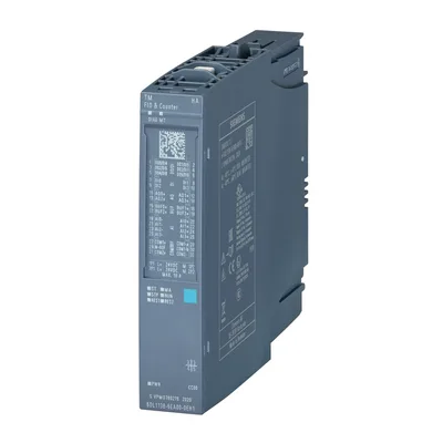
Product type designationFast Multi IO & Counter
HW functional statusFS04
Firmware versionV1.2
FW update possibleYes
Usable terminal blockType H1, M1, H0, M0 (for details see the system manual)
Color code for module-specific color-coded labelCC00
Product function
I&M dataYes; I&M0 to I&M3
Isochronous modeNo
Engineering with
STEP 7 TIA Portal configurable/integrated from versionV18
STEP 7 configurable/integrated from versionV5.6 with HSP 298 or higher
PCS 7 configurable/integrated from versionV9.1 SP1
SPPA-T3000 can be configured/integrated from versionV8.2 SP2
Operating mode
DIYes
CounterYes
DQYes
Redundancy
Redundancy capabilityYes; With TB type M1
CiR - Configuration in RUN
Reparameterization possible in RUNYes
Supply voltage
Rated value (DC)24 V
permissible range, lower limit (DC)19.2 V
permissible range, upper limit (DC)28.8 V
Reverse polarity protectionYes
Input current
Current consumption (rated value)150 mA; without load
Current consumption, max.2 A; At 24 V DC
from backplane bus 24 V DC, max.21 mA
Encoder supply
Number of outputs6; max. depending on parameterization
Output voltage (DC)24 V
Output voltage, min.18.2 V
Short-circuit protectionYes; per channel, electronic
24 V encoder supply
24 VYes
Short-circuit protectionYes; per channel, electronic
Output current per channel, max.0.5 A
Output current per module, max.2 A
Power loss
Power loss, typ.4 W
Address space per module
Address space per module, max.130 byte; Quick input and output: 30 bytes. Of which 13 bytes for inputs, 17 bytes for outputs. Quick input and output and counter function: 130 bytes. Of which 57 bytes for inputs, 73 bytes for outputs. Quick input and output and speed measurement: 42 bytes. Of which 25 bytes for inputs, 17 bytes for outputs
Hardware configuration
Mechanical coding elementYes; A, B coding; mounting position B8
Digital inputs
Number of digital inputs10; Of these, 6 combined DI/DQ
Digital inputs, parameterizableYes
Sourcing/sinking inputYes; DI0 ... DI3 (param.); sinking DIDQ4 ... DIDQ9
Input characteristic curve in accordance with IEC 61131, type 1Yes
Pulse extensionYes
Length2 s; off, 50 ms, 100 ms, 200 ms, 500 ms, 1 s, 2 s
Digital input functions, parameterizable
Gate start/stopYes; Selectable: Standard DI, encoder signals A, B, N, gate start, gate stop, set counter
Freely usable digital inputYes
CounterYes
— Number, max.4
— Counting frequency, max.70 kHz; 70 kHz for DI; 7 kHz for DI/DQ; each for P/M encoder and 50 m cable length; 10 kHz for DI; 0.7 kHz for DI/DQ; each for P encoder and 50 m cable length
— Counting width32 bit
— Counting direction up/downYes
— Number, max.4
Input voltage
Rated value (DC)24 V
for signal "0"0 ... 5 V
for signal "1"+11 to +30V
Input current
for signal "1", typ.2.6 mA; 2.6 mA DI, 3.5 mA DIDQ
for standard inputs
— parameterizableYes; 0.05 / 0.1 / 0.4 / 0.8 / 1.6 / 3.2 / 12.8 / 20 ms (in each case + delay of 30 to 500 µs, depending on line length)
for technological functions
— parameterizableYes; Adjustable filter: 5 µs, 25 µs
Cable length
shielded, max.1 000 m
Digital outputs
Number of digital outputs6; max. depending on parameterization
Current-sinkingNo
Current-sourcingYes
Digital outputs, parameterizableYes
Short-circuit protectionYes
Response threshold, typ.0.95 A
Open-circuit detectionYes
Response threshold, typ.45 mA
Overload protectionYes
Response threshold, typ.950 mA
Limitation of inductive shutdown voltage toL+ -(37 to 41V)
Controlling a digital inputYes
Digital output functions, parameterizable
Switching tripped by comparison valuesYes; As output signal of a high-speed counter
— HysteresisYes; Parameterizable
Freely usable digital outputYes
Switching capacity of the outputs
with resistive load, max.0.5 A
Load resistance range
lower limit48 Ω
Output voltage
for signal "1", min.18.1 V
Output current
for signal "1" rated value0.5 A
Output delay with resistive load
"0" to "1", typ.1 ms
"1" to "0", typ.100 µs
Parallel switching of two outputs
for logic linksNo
for upratingNo
for redundant control of a loadYes
Switching frequency
with resistive load, max.800 Hz
Total current of the outputs
Current per channel, max.0.5 A
Current per module, max.2 A
Cable length
shielded, max.1 000 m
Analog inputs
Number of analog inputs4
permissible input voltage for voltage input (destruction limit), max.30 V
permissible input current for current input (destruction limit), max.50 mA; Protection available against destruction
Input ranges (rated values), voltages
0 to +10 VYes
— Input resistance (0 to 10 V)100 kΩ
-10 V to +10 VYes
— Input resistance (-10 V to +10 V)100 kΩ
Input ranges (rated values), currents
0 to 20 mAYes; 0 mA or 4 mA to 20 mA
— Input resistance (0 to 20 mA)70 Ω
-20 mA to +20 mAYes
— Input resistance (-20 mA to +20 mA)70 Ω
4 mA to 20 mAYes; and 0 to 20 mA
— Input resistance (4 mA to 20 mA)70 Ω
Cable length
shielded, max.600 m
Analog outputs
Number of analog outputs8; 4 AQ-I, 4 AQ-U
Voltage output, short-circuit protectionYes; per channel, electronic to chassis
Voltage output, short-circuit current, max.10 mA
Current output, no-load voltage, max.24 V
Output ranges, voltage
-10 V to +10 VYes
Output ranges, current
0 to 20 mAYes
-20 mA to +20 mAYes; ±30 mA, ±50 mA
4 mA to 20 mAYes
Connection of actuators
for voltage output two-wire connectionYes
Load impedance (in rated range of output)
with current outputs, max.330 Ω; 150 ohms at ±50 mA
Analog value generation for the inputs
Measurement principleintegrating (Sigma-Delta)
Integration and conversion time/resolution per channel
Resolution with overrange (bit including sign), max.24 bit
Smoothing of measured values
parameterizableYes
Step: NoneYes
Step: lowYes
Step: MediumYes
Step: HighYes
Integration and conversion time/resolution per channel
Resolution with overrange (bit including sign), max.16 bit
Connection of signal encoders
for voltage measurementYes
for current measurement as 2-wire transducerYes
Connectable encoders
Single contact / changeover contact unconnectedYes
2-wire sensorYes
— permissible quiescent current (2-wire sensor), max.1.5 mA
Errors/accuracies
Linearity error (relative to input range), (+/-)0.05 %
Temperature error (relative to input range), (+/-)0.0025 %/K
Crosstalk between the inputs, min.60 dB
Operational error limit in overall temperature range
Voltage, relative to input range, (+/-)0.3 %
Current, relative to input range, (+/-)0.3 %
Interrupts/diagnostics/status information
Diagnostics functionYes
Substitute values connectableYes
Alarms
Diagnostic alarmYes
Diagnoses
Monitoring the supply voltageYes
Wire breakYes; AI 4 ... 20 mA, AQ, DQ, DI 0 ... 3
Short-circuit to groundYes; Encoder supply to M, channel by channel
Short-circuit to L+Yes; Analog inputs
Group errorYes
Overflow/UnderflowYes
Diagnostics indication LED
RUN LEDYes; green LED
MAINT LEDYes; Yellow LED
Monitoring of the supply voltage (PWR-LED)Yes; green PWR LED
for module diagnosticsYes; green/red DIAG LED
Integrated Functions
Frequency measurementYes; Speed measurement
Counting functions
Continuous countingYes
Counter response parameterizableYes
Hardware gate via digital inputYes
Software gateYes
Measuring functions
Dynamic measurement period adjustmentYes; Speed measurement
Measuring range
— Frequency measurement, min.0.1 Hz
— Frequency measurement, max.70 kHz; 70 kHz for DI; 7 kHz for DI/DQ; each for P/M encoder and 50 m cable length; 10 kHz for DI; 0.7 kHz for DI/DQ; each for P encoder and 50 m cable length
Potential separation channels
between the channels and backplane busYes
Permissible potential difference
between different circuits75 V DC/60 V AC between L+ and backplane bus
Isolation
Isolation tested with1 500 V DC/1 min, type test
Ambient temperature during operation
horizontal installation, min.-40 °C
horizontal installation, max.70 °C; Observe derating
vertical installation, min.-40 °C
vertical installation, max.60 °C
Altitude during operation relating to sea level
Installation altitude above sea level, max.3 500 m
Dimensions
Width22.5 mm
Height115 mm
Depth138 mm
Weights
Weight, approx.200 g