General information
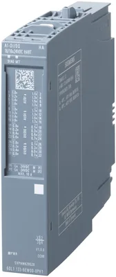
Product type designationAI-DI 16/DQ 16x24VDC HART HA
Firmware versionV1.1
FW update possibleYes; The firmware update can take more than 5 minutes.
Usable terminal blocktype H1, M1, N0, H0, M0 (for details see the system manual)
Color code for module-specific color-coded labelCC00
Product function
I&M dataYes; I&M0 to I&M3
Engineering with
STEP 7 TIA Portal configurable/integrated from versionV16
STEP 7 configurable/integrated from versionV5.6
PCS 7 configurable/integrated from versionV9.0
PCS neo can be configured/integrated from versionV3.0
PROFINET from GSD version/GSD revisionGSDML V2.3
Operating mode
AIYes
AQNo
HARTYes
DIYes
CounterYes
DQYes
DQ with energy-saving functionNo
PWMNo
OversamplingNo
MSINo
MSONo
Redundancy
Redundancy capabilityYes; With TB type M1
CiR - Configuration in RUN
Reparameterization possible in RUNYes
Supply voltage
Rated value (DC)24 V
permissible range, lower limit (DC)19.2 V
permissible range, upper limit (DC)28.8 V
Reverse polarity protectionYes
Input current
Current consumption (rated value)80 mA; without sensor supply
Current consumption, max.90 mA; without sensor supply
Encoder supply
Number of outputs16
Output voltage, min.18.2 V
Short-circuit protectionYes; per channel, electronic
24 V encoder supply
24 VYes
Short-circuit protectionYes; Electronic (response threshold 0.7 A to 1.5 A)
Output current per channel, max.0.5 A
Output current per module, max.2 A
Power loss
Power loss, typ.4.5 W; without sensor supply
Address space per module
Address space per module in mixed operation, max.42 byte; 34 bytes for inputs, 2 bytes for outputs and 6 bytes for QI information
Address space per module in mixed operation with HART, max.82 byte; 34-byte inputs, 2-byte outputs, 40 bytes for HART secondary variables, and 6 bytes for QI information
Address space per module in mixed operation with multiHART, max.70 byte; 34-byte inputs, 2-byte outputs, 24-byte HART inputs, 4-byte HART outputs, and 6 bytes for QI information
Address space per module in purely digital operation, max.26 byte; 2 bytes for inputs, 2 bytes for outputs, 18 bytes for high-precision time stamping and 4 bytes for QI information.
Address space per module in purely digital operation with counter/frequency measurement, max.88 byte; 2 bytes for inputs, 2 bytes for outputs, 40 bytes for counter input data, 40 bytes for counter output data and 4 bytes for QI information.
Digital inputs
Number of digital inputs16
Digital inputs, parameterizableYes
Sourcing/sinking inputYes; P-reading
Input characteristic curve in accordance with IEC 61131, type 1Yes
Input characteristic curve in accordance with IEC 61131, type 2No
Input characteristic curve in accordance with IEC 61131, type 3Yes
Pulse extensionYes; off, 50 ms, 100 ms, 200 ms, 500 ms, 1 s, 2 s
Time stampYes; Resolution 10 ms
Time stamp (with precision of 1 ms)Yes; Resolution 1ms
Digital input functions, parameterizable
Gate start/stopYes; Partner channel of n+8 counter
Freely usable digital inputYes; Parameterizable input filter
CounterYes; Incl. frequency measurement
— Number, max.8; Counter channel n=0 ... 7
— Counting frequency, max.5 kHz
— Counting width32 bit; Without sign
— Counting direction up/downYes; Up
Input voltage
Rated value (DC)24 V
for signal "0"-30 to +5 V
for signal "1"+11 to +30V
Input current
for signal "1", typ.2.5 mA
for standard inputs
— parameterizableYes; 0.05 / 0.1 / 0.4 / 0.8 / 1.6 / 3.2 / 12.8 / 20 ms (in each case + delay of 30 to 500 µs, depending on line length)
Cable length
shielded, max.1 000 m
unshielded, max.600 m
Digital outputs
Number of digital outputs16
Current-sinkingNo
Current-sourcingYes
Digital outputs, parameterizableYes
Short-circuit protectionYes; Response threshold 0.7 A to 1.3 A
Open-circuit detectionYes
Overload protectionYes
Limitation of inductive shutdown voltage toL+ -(37 to 41V)
Controlling a digital inputYes
Switching capacity of the outputs
with resistive load, max.0.5 A
on lamp load, max.5 W
Load resistance range
lower limit48 Ω
upper limit12 kΩ
Output current
for signal "1" rated value0.5 A
for signal "0" residual current, max.0.7 mA
Output delay with resistive load
"0" to "1", typ.50 µs
"1" to "0", typ.100 µs
Parallel switching of two outputs
for upratingNo
for redundant control of a loadYes
Switching frequency
with resistive load, max.100 Hz
on lamp load, max.10 Hz
Total current of the outputs
Current per channel, max.0.5 A
Current per module, max.2 A
Cable length
shielded, max.1 000 m
unshielded, max.600 m
Analog inputs
Number of analog inputs16
permissible input current for current input (destruction limit), max.30 mA
Input ranges (rated values), currents
0 to 10 mAYes
— Input resistance (0 to 10 mA)250 Ω
0 to 20 mAYes; 16 bit incl. sign
— Input resistance (0 to 20 mA)250 Ω
4 mA to 20 mAYes; 16 bit incl. sign
— Input resistance (4 mA to 20 mA)250 Ω
Analog value generation for the inputs
Measurement principleintegrating (Sigma-Delta)
Integration and conversion time/resolution per channel
Resolution with overrange (bit including sign), max.16 bit; Resolution with overrange (bit including sign), max. 16 bits, exception: 15 bits at 60 Hz interference suppression and 0 to 10 mA
Integration time, parameterizableYes; channel by channel
Smoothing of measured values
parameterizableYes; none, weak, medium, strong, channel-by-channel
Connection of signal encoders
for current measurement as 2-wire transducerYes
Connectable encoders
2-wire sensorYes
— permissible quiescent current (2-wire sensor), max.1.5 mA
Errors/accuracies
Linearity error (relative to input range), (+/-)0.01 %
Temperature error (relative to input range), (+/-)0.005 %/K
Crosstalk between the inputs, min.60 dB
Repeat accuracy in steady state at 25 °C (relative to input range), (+/-)0.05 %
Operational error limit in overall temperature range
Current, relative to input range, (+/-)0.5 %
Basic error limit (operational limit at 25 °C)
Current, relative to input range, (+/-)0.1 %
Interrupts/diagnostics/status information
Diagnostics functionYes
Substitute values connectableYes
Alarms
Diagnostic alarmYes
Maintenance interruptYes
Limit value alarmYes; two upper and two lower limit values in each case
Hardware interruptYes; Parameterizable, channels 0 to 15, rising/falling edge
Diagnoses
Monitoring the supply voltageYes
Wire breakYes; channel by channel
Short-circuit to groundYes; Encoder supply to M, channel by channel
Group errorYes
Overflow/UnderflowYes; channel by channel
Diagnostics indication LED
MAINT LEDYes; Yellow LED
Monitoring of the supply voltage (PWR-LED)Yes; green PWR LED
Channel status displayNo
for channel diagnosticsNo
for module diagnosticsYes; green/red DIAG LED
Integrated Functions
Frequency measurementYes
Number of frequency meters8
Counting functions
Continuous countingYes
Counter response parameterizableYes
Hardware gate via digital inputYes; Via partner channel (digital input n+8)
Software gateYes
Measuring functions
Dynamic measurement period adjustmentYes
Measuring range
— Frequency measurement, min.0.1 Hz
— Frequency measurement, max.5 kHz
Accuracy
— Frequency measurement100 ppm; depending on measuring interval and signal evaluation
Potential separation channels
between the channelsNo
between the channels and backplane busYes
Between the channels and load voltage L+No
Isolation
Isolation tested with1 500 V DC/1 min, type test
Ambient temperature during operation
horizontal installation, min.-40 °C
horizontal installation, max.70 °C; Observe derating
vertical installation, min.-40 °C
vertical installation, max.60 °C; Observe derating
Dimensions
Width22.5 mm
Height115 mm
Depth138 mm
Weights
Weight, approx.150 g