General information
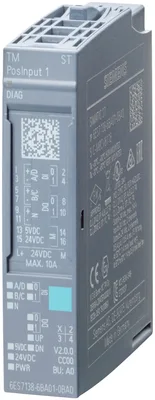
Product type designationTM PosInput 1
FW update possibleYes
based on6ES7138-6BA01-0BA0
usable BaseUnitsBU type A0
Color code for module-specific color-coded labelCC00
Product function
I&M dataYes; I&M0 to I&M3
Isochronous modeYes
Engineering with
STEP 7 TIA Portal configurable/integrated from versionsee entry ID: 109746275
Supply voltage
Rated value (DC)24 V
Load voltage L+
Rated value (DC)24 V
permissible range, lower limit (DC)19.2 V
permissible range, upper limit (DC)28.8 V
Reverse polarity protectionYes
Input current
Current consumption, max.75 mA; without load
Encoder supply
Number of outputs2
5 V encoder supply
5 VYes
Short-circuit protectionYes; electronic/thermal
Output current, max.300 mA; Total current of all encoders
24 V encoder supply
24 VYes; L+ (-0.8 V)
Short-circuit protectionYes; electronic/thermal
Output current, max.300 mA; Total current of all encoders
Power loss
Power loss, typ.1.5 W
Address space per module
Inputs16 byte; 4 bytes in Fast mode
Outputs12 byte; 4 bytes for Motion Control, 0 bytes for Fast mode
Hardware configuration
Automatic encodingYes
Mechanical coding elementYes
Type of mechanical coding elementtype B
Digital inputs
Number of digital inputs2
Digital inputs, parameterizableYes
Input characteristic curve in accordance with IEC 61131, type 3Yes
Digital input functions, parameterizable
Gate start/stopYes; only for pulse and incremental encoders
CaptureYes
SynchronizationYes; only for pulse and incremental encoders
Freely usable digital inputYes
Input voltage
Rated value (DC)24 V
for signal "0"-5 ... +5 V
for signal "1"+11 to +30V
permissible voltage at input, min.-30 V; -5 V continuous, -30 V brief reverse polarity protection
permissible voltage at input, max.30 V
Input current
for signal "1", typ.2.5 mA
for standard inputs
— parameterizableYes; none / 0.05 / 0.1 / 0.4 / 0.8 / 1.6 / 3.2 / 12.8 / 20 ms
for technological functions
— parameterizableYes
Cable length
shielded, max.1 000 m
unshielded, max.600 m
Digital outputs
Type of digital outputTransistor
Number of digital outputs2
Digital outputs, parameterizableYes
Short-circuit protectionYes; electronic/thermal
Response threshold, typ.1 A
Limitation of inductive shutdown voltage toL+ (-53 V)
Controlling a digital inputYes
Digital output functions, parameterizable
Switching tripped by comparison valuesYes
Freely usable digital outputYes
Switching capacity of the outputs
with resistive load, max.0.5 A; Per digital output
on lamp load, max.5 W
Load resistance range
lower limit48 Ω
upper limit12 kΩ
Output voltage
for signal "1", min.23.2 V; L+ (-0.8 V)
Output current
for signal "1" rated value0.5 A; Per digital output
for signal "1" permissible range, max.0.6 A; Per digital output
for signal "1" minimum load current2 mA
for signal "0" residual current, max.0.5 mA
Output delay with resistive load
"0" to "1", max.50 µs
"1" to "0", max.50 µs
Switching frequency
with resistive load, max.10 kHz
with inductive load, max.0.5 Hz; Acc. to IEC 60947-5-1, DC-13; observe derating curve
on lamp load, max.10 Hz
Total current of the outputs
Current per module, max.1 A
Cable length
shielded, max.1 000 m
unshielded, max.600 m
Encoder signals, incremental encoder (symmetrical)
Input voltageRS 422
Input frequency, max.1 MHz
Counting frequency, max.4 MHz; with quadruple evaluation
Cable length, shielded, max.32 m; at 1 MHz
Signal filter, parameterizableYes
Incremental encoder with A/B tracks, 90° phase offsetYes
Incremental encoder with A/B tracks, 90° phase offset and zero trackYes
pulse encoderYes
Pulse encoder with directionYes
pulse encoder with one impulse signal per count directionYes
Encoder signals, incremental encoder (asymmetrical)
Input voltage5 V TTL (push-pull encoders only)
Input frequency, max.1 MHz
Counting frequency, max.4 MHz; with quadruple evaluation
Signal filter, parameterizableYes
Incremental encoder with A/B tracks, 90° phase offsetYes
Incremental encoder with A/B tracks, 90° phase offset and zero trackYes
pulse encoderYes
pulse encoder with directionYes
pulse encoder with one impulse signal per count directionYes
Encoder signals, absolute encoder (SSI)
Input signalto RS-422
Telegram length, parameterizable10 ... 40 bit
Clock frequency, max.2 MHz; 125 kHz, 250 kHz, 500 kHz, 1 MHz, 1.5 MHz or 2 MHz
Binary codeYes
Gray codeYes
Cable length, shielded, max.320 m; Cable length, RS-422 SSI absolute encoders, Siemens type 6FX2001-5, 24 V supply: 125 kHz, 320 meters shielded, max.; 250 kHz, 160 meters shielded, max.; 500 kHz, 60 meters shielded, max.; 1 MHz, 20 meters shielded, max. 1.5 MHz, 10 meters shielded, max.; 2 MHz, 8 meters shielded, max.
Parity bit, parameterizableYes
Monoflop time16, 32, 48, 64 µs & automatic
MultiturnYes
SingleturnYes
Interface types
TTL 5 VYes; push-pull encoders only
RS 422Yes
Interfaces
Number of RS 485 interfaces0
Interrupts/diagnostics/status information
Substitute values connectableYes; Parameterizable
Alarms
Diagnostic alarmYes
Hardware interruptYes
Diagnoses
Monitoring the supply voltageYes
Wire breakYes
Short-circuitYes
A/B transition error at incremental encoderYes
Telegram error at SSI encoderYes
Group errorYes
Diagnostics indication LED
Monitoring of the supply voltage (PWR-LED)Yes; green PWR LED
Channel status displayYes; green LED
for module diagnosticsYes; green/red DIAG LED
Status indicator forward counting (green)Yes
Status indicator backward counting (green)Yes
Integrated Functions
CounterYes
Number of counters1
Counting frequency, max.4 MHz; with quadruple evaluation
Fast modeYes
Counting functions
Can be used with TO High_Speed_CounterYes; only for pulse and incremental encoders
Continuous countingYes
Counter response parameterizableYes
Hardware gate via digital inputYes
Software gateYes
Event-controlled stopYes
Synchronization via digital inputYes
Counting range, parameterizableYes
Comparator
— Number of comparators2
— Direction dependencyYes
— Can be changed from user programYes
Position detection
Incremental acquisitionYes
Absolute acquisitionYes
Suitable for S7-1500 Motion ControlYes
Measuring functions
Measuring time, parameterizableYes
Dynamic measurement period adjustmentYes
Number of thresholds, parameterizable2
Measuring range
— Frequency measurement, min.0.04 Hz
— Frequency measurement, max.4 MHz
— Cycle duration measurement, min.0.25 µs
— Cycle duration measurement, max.25 s
Accuracy
— Frequency measurement100 ppm; depending on measuring interval and signal evaluation
— Cycle duration measurement100 ppm; depending on measuring interval and signal evaluation
— Velocity measurement100 ppm; depending on measuring interval and signal evaluation
Potential separation channels
between the channels and backplane busYes
Isolation
Isolation tested with750 V DC (type test) and according to EN 50155 (routine test)
Standards, approvals, certificates
Suitable for safety functionsNo
Railway application
EN 50121-3-2Yes; EMC for rail vehicles
EN 50121-4Yes; EMC for signal and telecommunications systems
EN 50121-5Yes; EMC for fixed installations and railway power supply equipment (shielded cables required)
EN 50124-1Yes; Railway applications - overvoltage category OV2; pollution degree PD2; rated surge voltage UNi = 0.5 kV; UNm = 24 V DC
EN 50125-1Yes; Rail vehicles - see ambient conditions
EN 50125-2Yes; Stationary electrical equipment - see ambient conditions
EN 50125-3Yes; Signal and telecommunications systems - see ambient conditions; vibrations and shocks: Application point outside of tracks (1 m to 3 m away from track)
EN 50155Yes; Rail vehicles - temperature class OT2, ST1/ST2, horizontal mounting position
EN 61373Yes; Rail vehicles - vibrations and shocks: Category 1 Class A/B
Fire protection acc. to EN 45545-2Yes; For proof of conformity, see Service & Support
Ambient temperature during operation
horizontal installation, min.-40 °C; = Tmin (incl. condensation/frost)
horizontal installation, max.60 °C; = Tmax; +70 °C for 10 min (OT2, ST1/ST2 acc. to EN 50155); +70 °C continuously with configured slots to the left and right of the module (OT4, ST1/ST2 acc. to EN 50155)
vertical installation, min.-40 °C; = Tmin
vertical installation, max.50 °C; = Tmax; see Derating BasedOn (e.g. manual)
ceiling installation, min.-40 °C; = Tmin
ceiling installation, max.50 °C; = Tmax
floor installation, min.-40 °C; = Tmin
floor installation, max.50 °C; = Tmax
Altitude during operation relating to sea level
Installation altitude above sea level, max.2 000 m
Ambient air temperature-barometric pressure-altitudeTmin ... Tmax at 1 140 hPa ... 795 hPa (-1 000 m ... +2 000 m)
Relative humidity
With condensation, tested in accordance with IEC 60068-2-38, max.100 %; RH incl. condensation / frost (no commissioning in bedewed state), horizontal installation
Coolants and lubricants
— Resistant to commercially available coolants and lubricantsYes; Incl. diesel and oil droplets in the air
Use in stationary industrial systems
— to biologically active substances according to EN 60721-3-3Yes; Class 3B2 mold, fungus and dry rot spores (with the exception of fauna); Class 3B3 on request
— to chemically active substances according to EN 60721-3-3Yes; Class 3C4 (RH < 75 %) incl. salt spray acc. to EN 60068-2-52 (severity degree 3); *
— to mechanically active substances according to EN 60721-3-3Yes; Class 3S4 incl. sand, dust, *
— Against mechanical environmental conditions acc. to EN 60721-3-3Yes; Class 3M8 using the SIPLUS Mounting Kit ET 200SP (6AG1193-6AA00-0AA0//6AG1193-6AB00-0AA0)
Use on land craft, rail vehicles and special-purpose vehicles
— to biologically active substances according to EN 60721-3-5Yes; Class 5B2 mold, fungus and dry rot spores (with the exception of fauna); Class 5B3 on request
— to chemically active substances according to EN 60721-3-5Yes; Class 5C3 (RH < 75 %) incl. salt spray acc. to EN 60068-2-52 (severity degree 3); *
— to mechanically active substances according to EN 60721-3-5Yes; Class 5S3 incl. sand, dust; *
— Against mechanical environmental conditions acc. to EN 60721-3-5Yes; Class 5M2 using the SIPLUS Mounting Kit ET 200SP (6AG1193-6AA00-0AA0/6AG1193-6AB00-0AA0)
— against mechanical environmental conditions in agriculture acc. to ISO 15003Yes; Level 1 (Location LE) using the SIPLUS Mounting Kit ET 200SP (6AG1193-6AA00-0AA0/6AG1193-6AB00-0AA0)
Usage in industrial process technology
— Against chemically active substances acc. to EN 60654-4Yes; Class 3 (excluding trichlorethylene)
— Environmental conditions for process, measuring and control systems acc. to ANSI/ISA-71.04Yes; Level GX group A/B (excluding trichlorethylene; harmful gas concentrations up to the limits of EN 60721-3-3 class 3C4 permissible); level LC3 (salt spray) and level LB3 (oil)
Remark
— Note regarding classification of environmental conditions acc. to EN 60721, EN 60654-4 and ANSI/ISA-71.04* The supplied plug covers must remain in place over the unused interfaces during operation!
Conformal coating
Coatings for printed circuit board assemblies acc. to EN 61086Yes; Class 2 for high reliability
Protection against fouling acc. to EN 60664-3Yes; Type 1 protection
Electronic equipment on rolling stock acc. to EN 50155Yes; class PC2 protective coating acc. to EN 50155
Military testing according to MIL-I-46058C, Amendment 7Yes; Discoloration of coating possible during service life
Qualification and Performance of Electrical Insulating Compound for Printed Board Assemblies according to IPC-CC-830AYes; Conformal coating, Class A
Decentralized operation
to SIMATIC S7-300Yes
to SIMATIC S7-400Yes
to SIMATIC S7-1200Yes
to SIMATIC S7-1500Yes
to standard PROFIBUS masterYes
to standard PROFINET controllerYes
Dimensions
Width15 mm
Height73 mm
Depth58 mm
Weights
Weight, approx.45 g
Other
Note:for use in railway applications, also observe the product information "SIPLUS extreme RAIL" A5E37661960A, Online Support article 109736776