General information
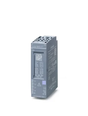
Product type designationAI Energy Meter CT ST
FW update possibleYes
based on6ES7134-6PA01-0BU0
usable BaseUnitsBU type U0
Color code for module-specific color-coded labelCC20
Supported power supply systemsTT, TN, IT
Product function
Voltage measurementYes
— without voltage transformerYes
— with voltage transformerYes
Current measurementYes; max. 3 + neutral conductor
— without current transformerNo
— with current transformerYes; 1 A or 5 A current transformer
— With Rogowski coilNo
— With current-voltage-converterNo
Energy measurementYes
Frequency measurementYes
Power measurementYes
Active power measurementYes
Reactive power measurementYes
Power factor measurementYes
Active factor measurementYes
Reactive power compensationYes
Line analysisNo
I&M dataYes; I&M0 to I&M3
Isochronous modeNo
Engineering with
STEP 7 TIA Portal configurable/integrated from versionsee entry ID: 109746275
Operating mode
Switching between operating modes in RUNYes; For module version 32 I/20 Q, it is possible to dynamically switch between 25 user data variants, 23 of which are pre-defined and 2 of which can be defined by the specific user
Cyclic measured value accessYes
Acyclic measured value accessYes
Fixed measured value setsYes
Freely definable measured value setsYes; For cyclic and acyclic measured value access
CiR - Configuration in RUN
Reparameterization possible in RUNYes
Calibration possible in RUNYes
Installation type/mounting
Mounting positionany
Supply voltage
Rated value (DC)24 V
permissible range, lower limit (DC)19.2 V
permissible range, upper limit (DC)28.8 V
Input current
Current consumption (rated value)12.5 mA
Current consumption, max.17 mA
Power loss
Power loss, typ.1 W; 3x 5 A input current, 3x 230 V AC
Address space per module
Inputs256 byte
Outputs20 byte
Hardware configuration
Automatic encodingYes
Mechanical coding elementYes
Type of mechanical coding elementtype C
Selection of BaseUnit for connection variants
2-wire connectionBU type U0
Operating hours counter
presentYes
Analog inputs
Cycle time (all channels), typ.50 ms; Time for consistent update of all measured and calculated values (cyclic und acyclic data)
Cable length
shielded, max.200 m
unshielded, max.200 m
Analog value generation for the inputs
Sampling frequency, max.2 048 kHz
Alarms
Diagnostic alarmYes
Limit value alarmYes
Hardware interruptYes; Monitoring of up to 16 freely selectable process values (exceeding or undershooting of value)
Diagnoses
Supply voltageYes
Hardware interrupt lostYes
Parameter assignment errorYes
Module faultYes
Channel not availableYes
Overflow/UnderflowYes
Overload currentYes
Diagnostics indication LED
Monitoring of the supply voltage (PWR-LED)Yes
Channel status displayYes; green LED
for channel diagnosticsYes; red Fn LED
for module diagnosticsYes; green/red DIAG LED
Measuring functions
Measuring procedure for voltage measurementTRMS
Measuring procedure for current measurementTRMS
Type of measured value acquisitionseamless
Curve shape of voltageSinusoidal or distorted
Buffering of measured variablesYes
Parameter length128 byte
Bandwidth of measured value acquisition3.2 kHz; Harmonics: 63 / 50 Hz, 52 / 60 Hz
Measuring range
— Frequency measurement, min.40 Hz
— Frequency measurement, max.70 Hz
Measuring inputs for voltage
— Measurable line voltage between phase and neutral conductor277 V
— Measurable line voltage between the line conductors480 V
— Measurable line voltage between phase and neutral conductor, min.3 V
— Measurable line voltage between phase and neutral conductor, max.300 V
— Measurable line voltage between the line conductors, min.6 V
— Measurable line voltage between the line conductors, max.519 V
— Internal resistance line conductor and neutral conductor1.5 MΩ
— Power consumption per phase60 mW; 300 V AC
— Impulse voltage resistance 1,2/50µs2.5 kV
— Measurement category for voltage measurement in accordance with IEC 61010-2-030CAT II
Measuring inputs for current
— measurable relative current (AC), min.1 %; Relative to measuring range; 1 A, 5 A
— measurable relative current (AC), max.100 %; Relative to the secondary rated current 5 A
— Continuous current with AC, maximum permissible5 A
— Apparent power consumption per phase for measuring range 5 A0.6 V·A
— Rated value short-time withstand current restricted to 1 s100 A
— Input resistance measuring range 0 to 5 A25 mΩ; At the terminal
— Surge strength10 A; for 1 minute
— Zero point suppression0 ... 20%, referred to the nominal current
Accuracy class according to IEC 61557-12
— Measured variable voltage0,2
— Measured variable current0,2
— Measured variable apparent power0.5
— Measured variable active power0.5
— Measured variable reactive power1
— Measured variable power factor0.5
— Measured variable active energy0.5
— Measured variable reactive energy1
— Measured variable neutral current0,2
— Measured variable phase angle±0.5 °; not covered by IEC 61557-12
— Measured variable frequency0.05; only valid for the permissible voltage measuring range
Potential separation channels
between the channelsNo
between the channels and backplane busYes
Between the channels and load voltage L+Yes; Including FE
Isolation
Isolation tested withBetween channels and backplane bus, 24 V supply: Routine test, 1 920 V AC, 2 s; between backplane bus and 24 V supply: Type test, 707 V DC
Ambient temperature during operation
horizontal installation, min.-40 °C; = Tmin (incl. condensation/frost)
horizontal installation, max.70 °C; = Tmax
vertical installation, min.-40 °C; = Tmin
vertical installation, max.50 °C; = Tmax
Altitude during operation relating to sea level
Installation altitude above sea level, max.3 000 m; Restrictions for installation altitudes > 2 000 m, see manual
Relative humidity
With condensation, tested in accordance with IEC 60068-2-38, max.100 %; RH incl. condensation / frost (no commissioning in bedewed state), horizontal installation
Coolants and lubricants
— Resistant to commercially available coolants and lubricantsYes; Incl. diesel and oil droplets in the air
Use in stationary industrial systems
— to biologically active substances according to EN 60721-3-3Yes; Class 3B2 mold, fungus and dry rot spores (with the exception of fauna); Class 3B3 on request
— to chemically active substances according to EN 60721-3-3Yes; Class 3C4 (RH < 75 %) incl. salt spray acc. to EN 60068-2-52 (severity degree 3); *
— to mechanically active substances according to EN 60721-3-3Yes; Class 3S4 incl. sand, dust, *
— Against mechanical environmental conditions acc. to EN 60721-3-3Yes; Class 3M8 using the SIPLUS Mounting Kit ET 200SP (6AG1193-6AA00-0AA0//6AG1193-6AB00-0AA0)
Use on ships/at sea
— to biologically active substances according to EN 60721-3-6Yes; Class 6B2 mold, fungal and dry rot spores (excluding fauna)
— to chemically active substances according to EN 60721-3-6Yes; Class 6C3 (RH < 75 %) incl. salt spray acc. to EN 60068-2-52 (severity degree 3); *
— to mechanically active substances according to EN 60721-3-6Yes; Class 6S3 incl. sand, dust; *
— Against mechanical environmental conditions acc. to EN 60721-3-6Yes; class 6M4 using the SIPLUS Mounting Kit ET 200SP (6AG1193-6AA00-0AA0/6AG1193-6AB00-0AA0)
Usage in industrial process technology
— Against chemically active substances acc. to EN 60654-4Yes; Class 3 (excluding trichlorethylene)
— Environmental conditions for process, measuring and control systems acc. to ANSI/ISA-71.04Yes; Level GX group A/B (excluding trichlorethylene; harmful gas concentrations up to the limits of EN 60721-3-3 class 3C4 permissible); level LC3 (salt spray) and level LB3 (oil)
Remark
— Note regarding classification of environmental conditions acc. to EN 60721, EN 60654-4 and ANSI/ISA-71.04* The supplied plug covers must remain in place over the unused interfaces during operation!
Conformal coating
Coatings for printed circuit board assemblies acc. to EN 61086Yes; Class 2 for high reliability
Protection against fouling acc. to EN 60664-3Yes; Type 1 protection
Military testing according to MIL-I-46058C, Amendment 7Yes; Discoloration of coating possible during service life
Qualification and Performance of Electrical Insulating Compound for Printed Board Assemblies according to IPC-CC-830AYes; Conformal coating, Class A
Dimensions
Width20 mm
Height73 mm
Depth58 mm
Weights
Weight, approx.45 g
Data for selecting a voltage transformer
Secondary side, max.300 V
Data for selecting a current transformer
Burden power current transformer x/1A, min.As a function of cable length and cross section, see device manual
Burden power current transformer x/5A, min.As a function of cable length and cross section, see device manual