General information
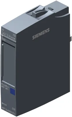
Product type designationAI 2xU/I 2-/4-wire HS
FW update possibleYes
based on6ES7134-6HB00-0DA1
usable BaseUnitsBU type A0, A1
Color code for module-specific color-coded labelCC00
Product function
I&M dataYes; I&M0 to I&M3
Isochronous modeYes; 125 µs
Measuring range scalableNo
Scalable measured valuesNo
Adjustment of measuring rangeNo
Engineering with
STEP 7 TIA Portal configurable/integrated from versionsee entry ID: 109746275
Operating mode
OversamplingYes; 2 channels per module
MSINo
CiR - Configuration in RUN
Reparameterization possible in RUNYes
Calibration possible in RUNNo
Supply voltage
Rated value (DC)24 V
permissible range, lower limit (DC)19.2 V
permissible range, upper limit (DC)28.8 V
Reverse polarity protectionYes
Input current
Current consumption (rated value)39 mA; without sensor supply
24 V encoder supply
24 VYes; For current measurement
Short-circuit protectionYes
Output current, max.20 mA; max. 50 mA per channel for a duration < 10 s
Power loss
Power loss, typ.0.95 W; without sensor supply
Address space per module
Address space per module, max.4 byte; + 1 byte for QI information (32 bytes in the oversampling operating mode)
Hardware configuration
Automatic encodingYes
Mechanical coding elementYes
Type of mechanical coding elementType A
Selection of BaseUnit for connection variants
2-wire connectionBU type A0, A1
4-wire connectionBU type A0, A1
Analog inputs
Number of analog inputs2; Differential inputs
For current measurement2
For voltage measurement2
permissible input voltage for voltage input (destruction limit), max.30 V
permissible input current for current input (destruction limit), max.50 mA
Cycle time (all channels), min.125 µs
Analog input with oversamplingYes
Values per cycle, max.16
Resolution, min.50 µs
Input ranges (rated values), voltages
0 to +10 VYes; 15 bit
— Input resistance (0 to 10 V)75 kΩ
1 V to 5 VYes; 13 bit
— Input resistance (1 V to 5 V)75 kΩ
-10 V to +10 VYes; 16 bit incl. sign
— Input resistance (-10 V to +10 V)75 kΩ
-5 V to +5 VYes; 15 bit incl. sign
— Input resistance (-5 V to +5 V)75 kΩ
Input ranges (rated values), currents
0 to 20 mAYes; 15 bit
— Input resistance (0 to 20 mA)130 Ω
-20 mA to +20 mAYes; 16 bit incl. sign
— Input resistance (-20 mA to +20 mA)130 Ω
4 mA to 20 mAYes; 14 bit
— Input resistance (4 mA to 20 mA)130 Ω
Cable length
shielded, max.1 000 m; 200 m for voltage measurement
Analog value generation for the inputs
Measurement principleActual value encryption (successive approximation)
Integration and conversion time/resolution per channel
Resolution with overrange (bit including sign), max.16 bit
Interference voltage suppression for interference frequency f1 in HzNo
Conversion time (per channel)10 µs
Smoothing of measured values
Number of smoothing levels7; none; 2-/4-/8-/16-/32-/64-fold
parameterizableYes
Connection of signal encoders
for voltage measurementYes
for current measurement as 2-wire transducerYes
— Burden of 2-wire transmitter, max.650 Ω
for current measurement as 4-wire transducerYes
Errors/accuracies
Linearity error (relative to input range), (+/-)0.03 %
Temperature error (relative to input range), (+/-)0.01 %/K
Crosstalk between the inputs, min.-50 dB
Repeat accuracy in steady state at 25 °C (relative to input range), (+/-)0.1 %
Operational error limit in overall temperature range
Voltage, relative to input range, (+/-)0.5 %
Current, relative to input range, (+/-)0.5 %
Basic error limit (operational limit at 25 °C)
Voltage, relative to input range, (+/-)0.2 %
Current, relative to input range, (+/-)0.2 %
Interference voltage suppression for f = n x (f1 +/- 1 %), f1 = interference frequency
Common mode voltage, max.35 V
Common mode interference, min.90 dB
Isochronous mode
Filtering and processing time (TCI), min.80 µs
Bus cycle time (TDP), min.125 µs; Starting from firmware Version V2.0.1
Alarms
Diagnostic alarmYes
Limit value alarmYes; two upper and two lower limit values in each case
Diagnoses
Wire breakYes; channel-by-channel, at 4 to 20 mA only
Short-circuitYes; channel-by-channel, at 1 to 5 V or for current measuring ranges short-circuit in encoder supply
Group errorYes
Overflow/UnderflowYes; channel by channel
Diagnostics indication LED
Monitoring of the supply voltage (PWR-LED)Yes; green PWR LED
Channel status displayYes; green LED
for channel diagnosticsYes; red LED
for module diagnosticsYes; green/red DIAG LED
Potential separation channels
between the channelsYes
between the channels and backplane busYes
between the channels and the power supply of the electronicsYes
Isolation
Isolation tested with707 V DC (type test)
Ambient temperature during operation
horizontal installation, min.-40 °C; = Tmin (incl. condensation/frost)
horizontal installation, max.60 °C; = Tmax; +70 °C with spacing modules (6AG1193-6BN00-7BA0) or configured slots to the left and right of the module
vertical installation, min.-40 °C; = Tmin
vertical installation, max.50 °C; = Tmax
Altitude during operation relating to sea level
Installation altitude above sea level, max.5 000 m
Ambient air temperature-barometric pressure-altitudeTmin ... Tmax at 1 140 hPa ... 795 hPa (-1 000 m ... +2 000 m) // Tmin ... (Tmax - 10 K) at 795 hPa ... 658 hPa (+2 000 m ... +3 500 m) // Tmin ... (Tmax -20 K) at 658 hPa ... 540 hPa (+3 500 m ... +5 000 m)
Relative humidity
With condensation, tested in accordance with IEC 60068-2-38, max.100 %; RH incl. condensation / frost (no commissioning in bedewed state), horizontal installation
Coolants and lubricants
— Resistant to commercially available coolants and lubricantsYes; Incl. diesel and oil droplets in the air
Use in stationary industrial systems
— to biologically active substances according to EN 60721-3-3Yes; Class 3B2 mold, fungus and dry rot spores (with the exception of fauna); Class 3B3 on request
— to chemically active substances according to EN 60721-3-3Yes; Class 3C4 (RH < 75 %) incl. salt spray acc. to EN 60068-2-52 (severity degree 3); *
— to mechanically active substances according to EN 60721-3-3Yes; Class 3S4 incl. sand, dust, *
— Against mechanical environmental conditions acc. to EN 60721-3-3Yes; Class 3M8 using the SIPLUS Mounting Kit ET 200SP (6AG1193-6AA00-0AA0)
Use on ships/at sea
— to biologically active substances according to EN 60721-3-6Yes; Class 6B2 mold and fungal spores (excluding fauna); Class 6B3 on request
— to chemically active substances according to EN 60721-3-6Yes; Class 6C3 (RH < 75 %) incl. salt spray acc. to EN 60068-2-52 (severity degree 3); *
— to mechanically active substances according to EN 60721-3-6Yes; Class 6S3 incl. sand, dust; *
— Against mechanical environmental conditions acc. to EN 60721-3-6Yes; Class 6M4 using the SIPLUS Mounting Kit ET 200SP (6AG1193-6AA00-0AA0)
Usage in industrial process technology
— Against chemically active substances acc. to EN 60654-4Yes; Class 3 (excluding trichlorethylene)
— Environmental conditions for process, measuring and control systems acc. to ANSI/ISA-71.04Yes; Level GX group A/B (excluding trichlorethylene; harmful gas concentrations up to the limits of EN 60721-3-3 class 3C4 permissible); level LC3 (salt spray) and level LB3 (oil)
Remark
— Note regarding classification of environmental conditions acc. to EN 60721, EN 60654-4 and ANSI/ISA-71.04* The supplied plug covers must remain in place over the unused interfaces during operation!
Conformal coating
Coatings for printed circuit board assemblies acc. to EN 61086Yes; Class 2 for high reliability
Protection against fouling acc. to EN 60664-3Yes; Type 1 protection
Military testing according to MIL-I-46058C, Amendment 7Yes; Discoloration of coating possible during service life
Qualification and Performance of Electrical Insulating Compound for Printed Board Assemblies according to IPC-CC-830AYes; Conformal coating, Class A
Dimensions
Width15 mm
Height73 mm
Depth58 mm
Weights
Weight, approx.32 g