product brand nameSIMOCODE
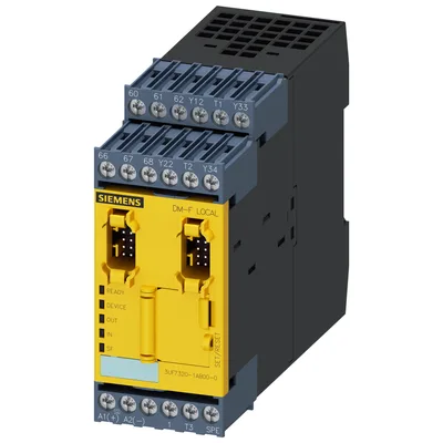
product designationFail-safe digital module
design of the productfor emergency off and safety doors
product type designationDM-FL
General technical data
EMERGENCY OFF functionYes
automatic startYes
light barrier monitoringYes
light array monitoringYes
protective door monitoringYes
magnetically operated switch monitoring NC-NOYes
magnetically operated switch monitoring NC-NCYes
pressure-sensitive mat monitoringYes
monitored start-upYes
input for thermistor connectionNo
digital inputYes
input for analog temperature sensorsNo
input for ground fault detectionNo
relay outputYes
consumed active power3 W
insulation voltage with degree of pollution 3 at AC rated value300 V
surge voltage resistance rated value4 000 V
shock resistance according to IEC 60068-2-2715 g / 11 ms
vibration resistance according to IEC 60068-2-61 ... 6 Hz: 15 mm, 6 ... 500 Hz: 2 g
operating frequency maximum360 1/y
at 24 V3 A
at 120 V3 A
at 240 V1.5 A
at 24 V4 A
at 60 V0.55 A
at 125 V0.22 A
at 250 V0.11 A
at 24 V3 A
at 120 V3 A
at 240 V1.5 A
at 24 V4 A
at 60 V0.55 A
at 125 V0.22 A
at 250 V0.11 A
mechanical service life (operating cycles) typical10 000 000
electrical endurance (operating cycles) typical100 000
buffering time in the event of power failure60 ms
after power failure typical8 s
after opening of the safety circuits typical250 ms
typical50 ms
maximum100 ms
at DC maximum100 ms
after power failure typical8 000 ms
after power failure maximum8 200 ms
backslide delay time after opening of the safety circuits typical50 ms
typical40 ms
maximum80 ms
reference code according to IEC 81346-2F
reference code according to IEC 81346-2:2019F
type of input characteristicType 2 in accordance with EN 61131-2
Substance Prohibitance (day/month/year)05/01/2012
SVHC substance nameLead CAS-No. 7439-92-1 Lead monoxide (lead oxide) CAS-No. 1317-36-8 2-methyl-1-(4-methylthiophenyl)-2-morpholinopropan-1-one CAS-No. 71868-10-5 Melamine CAS-No. 108-78-1 6,6'-di-tert-butyl-2,2'-methylenedi-p-cresol CAS-No. 119-47-1
Net Weight0.319 kg
Electromagnetic compatibility
EMC emitted interference according to IEC 60947-1class A
EMC immunity according to IEC 60947-1corresponds to degree of severity 3
due to burst according to IEC 61000-4-42 kV network connection / 1 kV control connection
due to conductor-earth surge according to IEC 61000-4-51 kV
due to conductor-conductor surge according to IEC 61000-4-50.5 kV
due to high-frequency radiation according to IEC 61000-4-610 V
field-based interference according to IEC 61000-4-310 V/m
electrostatic discharge according to IEC 61000-4-26 kV contact discharge / 8 kV air discharge
conducted HF interference emissions according to CISPR11corresponds to degree of severity A
field-bound HF interference emission according to CISPR11corresponds to degree of severity A
Inputs/ Outputs
parameterizable inputsYes
parameterizable outputsYes
number of inputs5
cascading input/functional switchingYes
feedback inputYes
start inputYes
of the sensor input minimum30 ms
of the ON pushbutton input minimum0.2 s
of the cascading input minimum0.2 s
number of digital inputs0
with a common reference potential4
type 1 acc. to IEC 61131No
type 2 acc. to IEC 61131Yes
number of analog inputs0
1-channel or 2-channel1
2-channel1
number of outputs2
number of semiconductor outputs0
2
as NO contact safety-related instantaneous contact2
number of analog outputs0
switching behaviormonostable
property of contacts of the relay outputsFail-safe NO contacts
wire length for digital signals maximum1 500 m
Product Function
position switch monitoringYes
EMERGENCY-OFF circuit monitoringYes
valve monitoringNo
opto-electronic protection device monitoringYes
tactile sensor monitoringNo
magnetically operated switch monitoringYes
proximity switch monitoringNo
safety-related circuitsYes
Installation/ mounting/ dimensions
mounting positionany
fastening methodscrew and snap-on mounting
height106 mm
width45 mm
depth124 mm
top40 mm
bottom40 mm
left0 mm
right0 mm
Connections/ Terminals
product component removable terminal for auxiliary and control circuitYes
type of electrical connection for auxiliary and control circuitscrew-type terminals
solid1x (0.5 ... 4.0mm²), 2x (0.5 ... 2.5 mm²)
finely stranded with core end processing1x (0.5 ... 2.5 mm²), 2x (0.5 ... 1.5 mm²)
for AWG cables solid1x (20 ... 12), 2x (20 ... 14)
for AWG cables stranded1x (20 ... 14), 2x (20 ... 16)
tightening torque with screw-type terminals0.8 ... 1.2 N·m
tightening torque [lbf·in] with screw-type terminals7 ... 10.3 lbf·in
Ambient conditions
1 maximum2 000 m
2 maximum3 000 m; max. +50 °C (no protective separation)
3 maximum4 000 m; max. +40 °C (no protective separation)
during operation-25 ... +60 °C
during storage-40 ... +80 °C
during transport-40 ... +80 °C
during operation according to IEC 607213K6 (no formation of ice, no condensation, relative humidity 10 ... 95%), 3C3 (no salt mist), 3S2 (sand must not get into the devices), 3M6
during storage according to IEC 607211K6 (no condensation, relative humidity 10 ... 95%), 1C2 (no salt mist), 1S2 (sand must not get into the devices), 1M4
during transport according to IEC 607212K2, 2C1, 2S1, 2M2
relative humidity during operation5 ... 95 %
contact rating of auxiliary contacts according to ULB300 / R300
Short-circuit protection
design of the fuse link for short-circuit protection of relay enabling circuits requiredgL/gG: 4 A
Safety related data
product function suitable for safety functionYes
safe stateSafety outputs switched off
diagnostics test interval by internal test function maximum28 800 s
stop category according to IEC 60204-10
failure rate [FIT] at rate of recognizable hazardous failures (λdd)868 FIT
failure rate [FIT] at rate of non-recognizable hazardous failures (λdu)7 FIT
at single-channel evaluation90 %
at 2-channel evaluation99 %
IEC 62061
at single-channel evaluation according to IEC 620611
at 2-channel evaluation according to IEC 620613
ISO 13849
at single-channel evaluation according to ISO 13849-1d
at 2-channel evaluation according to ISO 13849-1e
at single-channel evaluation according to ISO 13849-12
at 2-channel evaluation according to ISO 13849-14
IEC 61508
at single-channel evaluation according to IEC 615081
at 2-channel evaluation according to IEC 615083
safety device type according to IEC 61508-2Type B
at single-channel evaluation according to IEC 615080.00065
at 2-channel evaluation according to IEC 615082E-5
Safe failure fraction (SFF)99 %
at single-channel evaluation according to IEC 615080
at 2-channel evaluation according to IEC 615081
T1 value for proof test interval or service life according to IEC 6150820 a
Electrical Safety
touch protection against electrical shockfinger-safe
ATEX
certificate of suitability according to ATEX directive 2014/34/EUBVS 06 ATEX F001
explosion device group and category according to ATEX directive 2014/34/EUII (2) G, II (2 ) D, I (M2)
Galvanic isolation
(electrically) protective separation according to IEC 60947-1All circuits in SIMOCODE pro are with protective separation, i.e. they are designed with doubled creepage paths and clearances. NOTICE: The information in the "Protective Separation" test report, No. 2668, must be observed.
design of the electrical isolationProtective separation in accordance with IEC 60947-1 for all circuits, up to installation altitude of 2000 m
Control circuit/ Control
type of voltage of the control supply voltageDC
control supply voltage at DC rated value24 V
initial value0.8
full-scale value1.2
at 24 V8.3 A
at 24 V1 ms