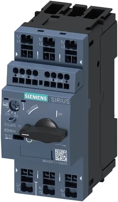
product brand nameSIRIUS
product designationCircuit breaker
design of the productFor motor protection
product type designation3RV2
General technical data
Product equipment of circuit breaker for motor protection complete unit with protection deviceYes
size of the circuit-breakerS00
size of contactor can be combined company-specificS00, S0
product function disconnector functionalityYes
product extension auxiliary switchYes
at AC in hot operating state7.25 W
at AC in hot operating state per pole2.4 W
type of calculation of power loss current-dependentquadratic
insulation voltage with degree of pollution 3 at AC rated value690 V
surge voltage resistance rated value6 kV
in networks with ungrounded star point between main and auxiliary circuit400 V
in networks with grounded star point between main and auxiliary circuit400 V
on the front according to IEC 60529IP20
on the frontIP20
of the terminalIP20
shock resistance according to IEC 60068-2-2725g / 11 ms
of the main contacts typical100 000
of auxiliary contacts typical100 000
electrical endurance (operating cycles) typical100 000
reference code according to IEC 81346-2Q
continuous current rated value6.3 A
Substance Prohibitance (day/month/year)10/01/2009
Net Weight362.6 g
Ambient conditions
installation altitude at height above sea level maximum2 000 m
during operation-20 ... +60 °C
during storage-50 ... +80 °C
during transport-50 ... +80 °C
temperature compensation-20 ... +60 °C
relative humidity during operation10 ... 95 %
Main circuit
number of poles for main current circuit3
adjustable current response value current of the current-dependent overload release4.5 ... 6.3 A
type of voltage for main current circuitAC
rated value690 V
rated value20 ... 690 V
at AC-3 rated value maximum690 V
at AC-3e rated value maximum690 V
operating frequency rated value50 ... 60 Hz
operational current rated value6.3 A
at AC-3 at 400 V rated value6.3 A
at AC-3e at 400 V rated value6.3 A
— at 230 V rated value1.5 kW
— at 400 V rated value2.2 kW
— at 500 V rated value3 kW
— at 690 V rated value4 kW
— at 230 V rated value1.5 kW
— at 400 V rated value2.2 kW
— at 500 V rated value3 kW
— at 690 V rated value4 kW
at AC-3 maximum15 1/h
at AC-3e maximum15 1/h
Auxiliary circuit
design of the auxiliary switchtransverse
type of voltage for auxiliary and control circuitAC/DC
number of NC contacts for auxiliary contacts1
number of NO contacts for auxiliary contacts1
number of CO contacts for auxiliary contacts0
at 24 V2 A
at 120 V0.5 A
at 125 V0.5 A
at 230 V0.5 A
at 24 V1 A
at 60 V0.15 A
Protective and monitoring functions
ground fault detectionNo
phase failure detectionYes
trip classCLASS 10
design of the overload releasethermal
protection function thermal overload protection (ANSI 49)Yes
at AC at 240 V rated value100 kA
at AC at 400 V rated value100 kA
at AC at 500 V rated value100 kA
at AC at 690 V rated value6 kA
at 240 V rated value100 kA
at 400 V rated value100 kA
at 500 V rated value100 kA
at 690 V rated value4 kA
response value current of instantaneous short-circuit trip unit82 A
UL/CSA ratings
at 480 V rated value6.3 A
at 600 V rated value6.3 A
— at 110/120 V rated value0.25 hp
— at 230 V rated value0.5 hp
— at 200/208 V rated value1 hp
— at 220/230 V rated value1.5 hp
— at 460/480 V rated value3 hp
— at 575/600 V rated value5 hp
contact rating of auxiliary contacts according to ULC300 / R300
UL File Number (CCN)E47705 (NLRV, NLRV7), E156943 (NKJH, NKJH7)
Short-circuit protection
product function short circuit protectionYes
design of the short-circuit tripmagnetic
for short-circuit protection of the auxiliary switch requiredFuse gL/gG: 10 A, miniature circuit breaker C 6 A (short-circuit current Ik < 400 A)
at 400 VgL/gG 50 A
at 500 VgL/gG 40 A
at 690 VgL/gG 35 A
certificate of suitability according to ATEX directive 2014/34/EUDMT 02 ATEX F 001
type of protection according to ATEX directive 2014/34/EUEx II (2) GD
Installation/ mounting/ dimensions
mounting positionany
fastening methodscrew and snap-on mounting onto 35 mm DIN rail according to DIN EN 60715
Mounting method of circuit breaker for Transformer protection, Generator protection and system protection optional standard bar mountingYes
height106 mm
width45 mm
depth97 mm
— forwards0 mm
— backwards0 mm
— upwards50 mm
— downwards50 mm
— at the side0 mm
— forwards0 mm
— backwards0 mm
— upwards50 mm
— at the side30 mm
— downwards50 mm
— forwards0 mm
— backwards0 mm
— upwards50 mm
— downwards50 mm
— at the side30 mm
— downwards30 mm
— upwards30 mm
— at the side9 mm
— downwards30 mm
— upwards30 mm
— at the side9 mm
— downwards30 mm
— upwards30 mm
— at the side9 mm
— downwards30 mm
— upwards30 mm
— at the side9 mm
— downwards50 mm
— upwards50 mm
— backwards0 mm
— at the side30 mm
— forwards0 mm
— downwards50 mm
— upwards50 mm
— backwards0 mm
— at the side30 mm
— forwards0 mm
Connections/ Terminals
product component removable terminal for auxiliary and control circuitNo
for main current circuitspring-loaded terminals
for auxiliary and control circuitspring-loaded terminals
arrangement of electrical connectors for main current circuitTop and bottom
— solid or stranded2x (0,5 ... 4 mm²)
— finely stranded with core end processing2x (0.5 ... 2.5 mm²)
— finely stranded without core end processing2x (0.5 ... 2.5 mm²)
for AWG cables for main contacts2x (20 ... 12)
solid or stranded0.5 ... 4 mm²
finely stranded with core end processing0.5 ... 2.5 mm²
finely stranded without core end processing0.5 ... 2.5 mm²
solid or stranded0.5 ... 2.5 mm²
finely stranded with core end processing0.5 ... 1.5 mm²
finely stranded without core end processing0.5 ... 1.5 mm²
— solid or stranded2x (0.5 ... 2.5 mm²)
— finely stranded with core end processing2x (0.5 ... 1.5 mm²)
— finely stranded without core end processing2x (0.5 ... 1.5 mm²)
for AWG cables for auxiliary contacts2x (20 ... 14)
AWG number as coded connectable conductor cross section for main contacts20 ... 12
AWG number as coded connectable conductor cross section for auxiliary contacts20 ... 14
design of screwdriver shaftDiameter 3 mm
size of the screwdriver tip3,0 x 0,5 mm
Safety related data
product function suitable for safety functionYes
safety-related switching onNo
safety-related switching OFFYes
service life maximum10 a
test wear-related service life necessaryYes
with low demand rate according to SN 3192040 %
with high demand rate according to SN 3192050 %
B10 value with high demand rate according to SN 319205 000
failure rate [FIT] with low demand rate according to SN 3192050 FIT
ISO 13849
device type according to ISO 13849-13
overdimensioning according to ISO 13849-2 necessaryYes
IEC 61508
safety device type according to IEC 61508-2Type A
for proof test interval or service life according to IEC 6150810 a
Electrical Safety
protection class IP on the front according to IEC 60529IP20
touch protection on the front according to IEC 60529finger-safe, for vertical contact from the front
Display
display version for switching statusHandle
Approvals Certificates
global warming potential [CO2 eq] / during manufacturing1.98 kg
global warming potential [CO2 eq] / during sales0.134 kg
global warming potential [CO2 eq] / during operation72.7 kg
global warming potential [CO2 eq] / after end of life-0.116 kg
global warming potential [CO2 eq] / total74.698 kg