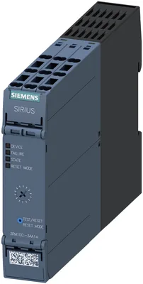
product brand nameSIRIUS
product categoryMotor starter
product designationDirect-on-line starter
design of the productwith electronic overload protection
product type designation3RM1
General technical data
equipment version according to IEC 60947-4-23
product functionDirect-on-line starter
intrinsic device protectionYes
for power supply reverse polarity protectionNo
suitability for operation device connector 3ZY12No
at AC in hot operating state per pole0.01 W
without load current share typical5.06 W
insulation voltage rated value500 V
overvoltage categoryIII
surge voltage resistance rated value6 kV
between main and auxiliary circuit500 V
between control and auxiliary circuit250 V
shock resistance6 g / 11 ms
vibration resistance1 ... 6 Hz, 15 mm; 20 m/s², 500 Hz
operating frequency maximum1 1/s
reference code according to IEC 81346-2Q
Substance Prohibitance (day/month/year)03/01/2017
SVHC substance nameLead CAS-No. 7439-92-1 Lead monoxide (lead oxide) CAS-No. 1317-36-8 2-methyl-1-(4-methylthiophenyl)-2-morpholinopropan-1-one CAS-No. 71868-10-5 Melamine CAS-No. 108-78-1 6,6'-di-tert-butyl-2,2'-methylenedi-p-cresol CAS-No. 119-47-1
Net Weight0.285 kg
direct startYes
reverse startingNo
product function short circuit protectionNo
Electromagnetic compatibility
EMC emitted interference according to IEC 60947-1class A
EMC immunity according to IEC 60947-1Class A
due to burst according to IEC 61000-4-43 kV / 5 kHz
due to conductor-earth surge according to IEC 61000-4-52 kV
due to conductor-conductor surge according to IEC 61000-4-51 kV
due to high-frequency radiation according to IEC 61000-4-610 V
field-based interference according to IEC 61000-4-310 V/m
electrostatic discharge according to IEC 61000-4-24 kV contact discharge / 8 kV air discharge
conducted HF interference emissions according to CISPR11Class B for domestic, business and commercial environments; Class A for industrial environments at 110 V DC
field-bound HF interference emission according to CISPR11Class B for domestic, business and commercial environments; Class A for industrial environments at 110 V DC
Safety related data
product function suitable for safety functionNo
safety-related switching onNo
safety-related switching OFFNo
test wear-related service life necessaryNo
ISO 13849
overdimensioning according to ISO 13849-2 necessaryNo
Electrical Safety
protection class IP on the front according to IEC 60529IP20
touch protection on the front according to IEC 60529finger-safe
Main circuit
number of poles for main current circuit3
design of the switching contactHybrid
design of the switching contact as NO contact for signaling functionOUT, electronic, 24 V DC, 15 mA
adjustable current response value current of the current-dependent overload release0.1 ... 0.5 A
minimum load [%]20 %; from set rated current
type of the motor protectionsolid-state
operating voltage rated value48 ... 500 V
relative symmetrical tolerance of the operating voltage10 %
operating frequency 1 rated value50 Hz
operating frequency 2 rated value60 Hz
relative symmetrical tolerance of the operating frequency10 %
at AC at 400 V rated value0.5 A
at AC-3 at 400 V rated value0.5 A
at AC-53a at 400 V at ambient temperature 40 °C rated value0.5 A
ampacity when starting maximum4 A
operating power for 3-phase motors at 400 V at 50 Hz0 ... 0.12 kW
Inputs/ Outputs
input voltage at digital input at DC rated value110 V
input voltage at digital input at AC rated value110 V
for signal <1> at DC1.5 mA
with signal <0> at DC0.25 mA
at 110 V0.2 mA
at 230 V0.4 mA
at 110 V1.1 mA
at 230 V2.3 mA
number of CO contacts for auxiliary contacts1
operational current of auxiliary contacts at AC-15 at 230 V maximum3 A
operational current of auxiliary contacts at DC-13 at 24 V maximum1 A
Control circuit/ Control
type of voltage of the control supply voltageAC/DC
at 50 Hz rated value110 ... 230 V
at 60 Hz rated value110 ... 230 V
relative negative tolerance of the control supply voltage at AC at 60 Hz15 %
relative positive tolerance of the control supply voltage at AC at 60 Hz10 %
at 50 Hz110 ... 230 V
at 60 Hz110 ... 230 V
1 rated value50 Hz
2 rated value60 Hz
relative negative tolerance of the control supply voltage at DC15 %
relative positive tolerance of the control supply voltage at DC10 %
control supply voltage 1 at DC rated value110 V
initial value0.85
full-scale value1.1
initial value0.85
full-scale value1.1
initial value0.85
full-scale value1.1
at 110 V in standby mode of operation16 mA
at 230 V in standby mode of operation9 mA
at 110 V when switching on55 mA
at 230 V when switching on33 mA
at 110 V during operation36 mA
at 230 V during operation22 mA
in standby mode of operation6 mA
during operation30 mA
at AC at 110 V1 200 mA
at AC at 230 V2 900 mA
at AC at 110 V at switching on of motor1 200 mA
at AC at 230 V at switching on of motor2 900 mA
at AC at 110 V1 ms
at AC at 230 V1 ms
at AC at 110 V at switching on of motor1 ms
at AC at 230 V at switching on of motor1 ms
— with bypass circuit2.1 W
— with bypass circuit5.06 W
Response times
ON-delay time60 ... 90 ms
OFF-delay time60 ... 90 ms
Power Electronics
at 40 °C rated value0.5 A
at 50 °C rated value0.5 A
at 55 °C rated value0.5 A
at 60 °C rated value0.5 A
Installation/ mounting/ dimensions
mounting positionvertical, horizontal, standing (observe derating)
fastening methodscrew and snap-on mounting onto 35 mm DIN rail
height100 mm
width22.5 mm
depth141.6 mm
— forwards0 mm
— backwards0 mm
— upwards50 mm
— downwards50 mm
— at the side0 mm
— forwards0 mm
— backwards0 mm
— upwards50 mm
— at the side3.5 mm
— downwards50 mm
Ambient conditions
installation altitude at height above sea level maximum4 000 m
during operation-25 ... +60 °C
during storage-40 ... +70 °C
during transport-40 ... +70 °C
environmental category during operation according to IEC 607213K6 (no ice formation, only occasional condensation), 3C3 (no salt mist), 3S2 (sand must not get into the devices), 3M6
relative humidity during operation10 ... 95 %
air pressure according to SN 31205900 ... 1 060 hPa
Communication/ Protocol
PROFINET IO protocolNo
PROFIsafe protocolNo
product function bus communicationNo
protocol is supported AS-Interface protocolNo
Connections/ Terminals
type of electrical connectionscrew-type terminals for main circuit, spring-loaded terminals (push-in) for control circuit
for main current circuitscrew-type terminals
for auxiliary and control circuitspring-loaded terminals (push-in)
wire length for motor unshielded maximum100 m
solid1x (0,5 ... 4 mm²), 2x (0,5 ... 2,5 mm²)
finely stranded with core end processing1x (0,5 ... 4 mm²), 2x (0,5 ... 1,5 mm²)
solid or stranded0.5 ... 4 mm²
finely stranded with core end processing0.5 ... 4 mm²
solid or stranded0.5 ... 1.5 mm²
finely stranded with core end processing0.5 ... 1 mm²
finely stranded without core end processing0.5 ... 1.5 mm²
— solid1x (0.5 ... 1.5 mm²), 2x (0.5 ... 1.5 mm²)
— finely stranded with core end processing1x (0,5 ... 1,0 mm²), 2x (0,5 ... 1,0 mm²)
— finely stranded without core end processing1x (0.5 ... 1.5 mm²), 2x (0.5 ... 1.5 mm²)
for AWG cables for auxiliary contacts1x (20 ... 16), 2x (20 ... 16)
AWG number as coded connectable conductor cross section for main contacts20 ... 12
AWG number as coded connectable conductor cross section for auxiliary contacts20 ... 16
UL/CSA ratings
operational current at AC at 480 V according to UL 5080.5 A