product brand nameSINOVA
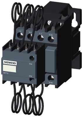
product designationCapacitor contactor
product type designation3MT7
General technical data
size of contactor3
product extension auxiliary switchNo
of main circuit with degree of pollution 3 rated value690 V
of auxiliary circuit with degree of pollution 3 rated value690 V
on the frontIP20
of the terminalIP00
of the contactor with added auxiliary switch block typical100 000
electrical endurance (operating cycles)100 000
reference code according to IEC 81346-2Q
Net Weight0.58 kg
Ambient conditions
installation altitude at height above sea level maximum2 000 m
during operation-5 ... +40 °C
during storage-60 ... +80 °C
Main circuit
number of poles3
number of NO contacts for main contacts3
at AC-6b at 440 V at ambient temperature 40 °C rated value29 A
at 240 V at 50 Hz 3 phase at ambient temperature 40 °C rated value12 kvar
at 400/415 V at 50 Hz 3 phase at ambient temperature 40 °C rated value20 kvar
at 440 V at 50/60 Hz 3 phase at ambient temperature 40 °C rated value22 kvar
at 600 V at 60 Hz 3 phase at ambient temperature 40 °C rated value25 kvar
at AC3 600 1/h
at 240 V maximum240 1/h
at 400 V maximum240 1/h
Control circuit/ Control
type of voltageAC
type of voltage of the control supply voltageAC
at 50 Hz rated value24 V
at 50 Hz rated value24 V
at 60 Hz rated value24 V
at 60 Hz rated value24 V
1 rated value50 Hz
2 rated value60 Hz
at 50 Hz0.85 ... 1.1
at 60 Hz0.85 ... 1.1
apparent pick-up power of magnet coil at AC90 V·A
apparent holding power of magnet coil at AC9 V·A
closing delay at AC14 ... 25 ms
opening delay at AC4 ... 15 ms
arcing time4 ... 15 ms
Auxiliary circuit
number of NC contacts for auxiliary contacts1
attachable0
instantaneous contact1
number of NO contacts for auxiliary contacts1
attachable0
instantaneous contact1
at 230 V2.09 A
at 400 V1.25 A
at 24 V5 A
at 110 V0.59 A
at 125 V0.59 A
at 220 V0.28 A
contact rating of auxiliary contacts according to ULA600 / P600
Short-circuit protection
— with type of coordination 1 requiredgG: 40 A (440 V, 50 kA)
for short-circuit protection of the auxiliary switch requiredgG: 10 A (500 V, 1 kA)
mounting position+/-180° rotation possible on vertical mounting surface; can be tilted forward and backward by +/- 22.5° on vertical mounting surface
fastening methodscrew and snap-on mounting onto 35 mm DIN rail according to DIN EN 50022
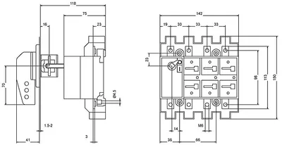
height140 mm
width56 mm
depth130 mm
required spacing for grounded parts at the side12 mm
Connections/ Terminals
for main current circuitscrew-type terminals
for auxiliary and control circuitscrew-type terminals
solid or stranded1x (1.5 ... 10 mm²), 2x (1.5 ... 6 mm²)
solid or stranded1.5 ... 10 mm²
finely stranded with pin-end connector10 ... 1.5 mm²
finely stranded without core end processing1.5 ... 6 mm²
solid or stranded1 ... 4 mm²
finely stranded with core end processing1 ... 4 mm²
finely stranded without core end processing1 ... 4 mm²
— solid or stranded1x (1 ... 4mm²), 2x (1 ... 4mm²)
— finely stranded with core end processing1x (1 ... 4 mm²), 2x (1 ... 4 mm²)
— finely stranded without core end processing1x (1 ... 4 mm²), 2x (1 ... 2.5 mm²)
for AWG cables for auxiliary contacts14
AWG number as coded connectable conductor cross section for main contacts12 ... 8
AWG number as coded connectable conductor cross section for auxiliary contacts14
for main contacts with screw-type terminals1.85 N·m
for auxiliary contacts with screw-type terminals1.2 N·m
for main contactsM4
of the auxiliary and control contactsM3.5
Safety related data
mirror contact according to IEC 60947-4-1No
positively driven operation according to IEC 60947-5-1No
Electrical Safety
protection class IP on the front according to IEC 60529IP20